Tool Assembly

a tool and assembly technology, applied in the field of tools, can solve the problems of large dead weight, large length, and high consumption of material in the manufacturing process, and achieve the effect of reducing the axial length of the working member

Inactive Publication Date: 2009-04-21
TAEGUTEC
View PDF17 Cites 5 Cited by
  • Summary
  • Abstract
  • Description
  • Claims
  • Application Information

AI Technical Summary

Benefits of technology

[0014]Accordingly, the present invention is conceived to solve the aforementioned problems caused by a coupling structure between a working member and a coupling member, an object of the present invention is to provide a tool assembly being capable of reducing considerably an axial length of a working member (tool), in particular, a length of a male spigot to be coupled with a coupling member.
[0015]Another object of the present invention is to provide a tool assembly in which a male spigot of a working member (tool) having a short length can be securely coupled with a coupling member to transmit a torque to a working member without generating a loss.
[0017]The male spigot has a tapered surface formed on a side thereof and a through hole communicated with the cavity is formed on a side of the first section of the coupling member, and so an end of a coupling screw coupled with the through holes is capable of pressurizing the tapered surface of the male spigot received in the cavity.

Problems solved by technology

The tool assembly having the great length has the problems of a great dead weight, a high consumption of material in the manufacturing process and an extra great space in connection with storage and transportation.
In addition, the great length of the tool assembly means that the tool assembly is set in a vibration circumstance during the machining process.

Method used


Image

  • Tool Assembly
  • Tool Assembly
  • Tool Assembly

Examples


Embodiment Construction

[0027]Hereinafter, the preferred embodiment of the present invention is described in detail with reference with the accompanying drawings.

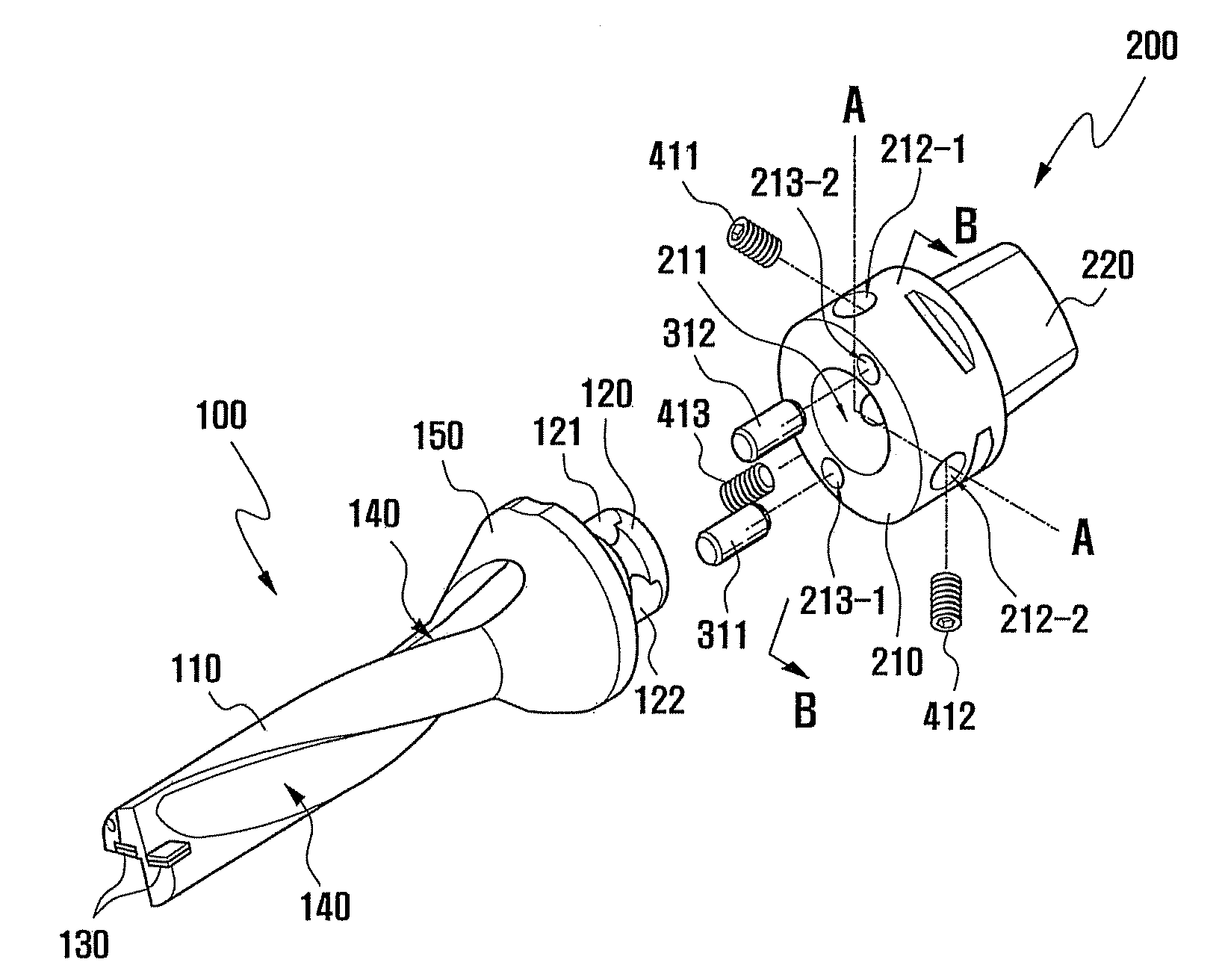
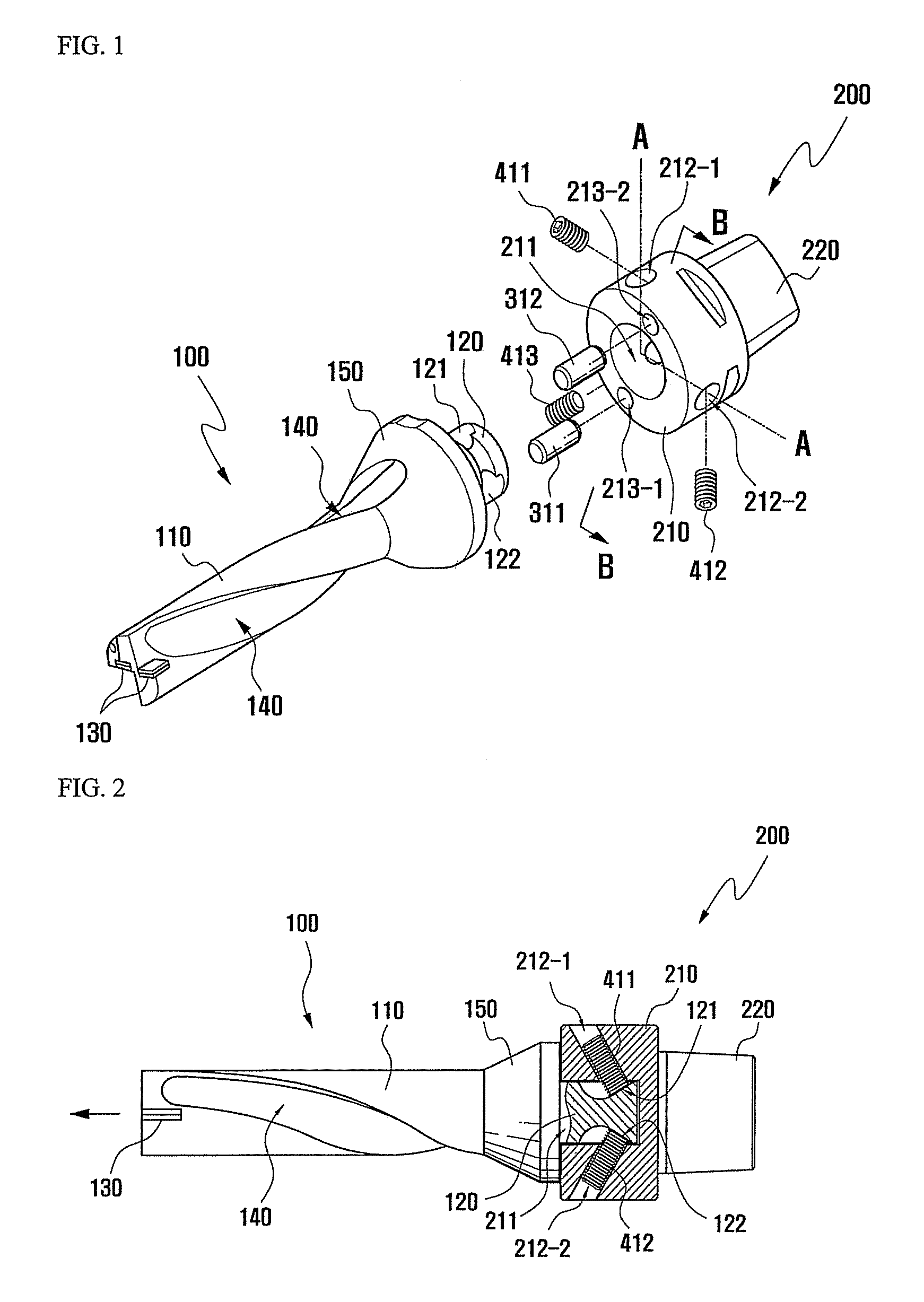
[0028]FIG. 1 is an exploded perspective view of a tool assembly according to one embodiment of the present invention. The tool assembly according to one embodiment of the present invention comprises a working member 100 (hereinafter, referred to as “tool”) and a coupling member 200.

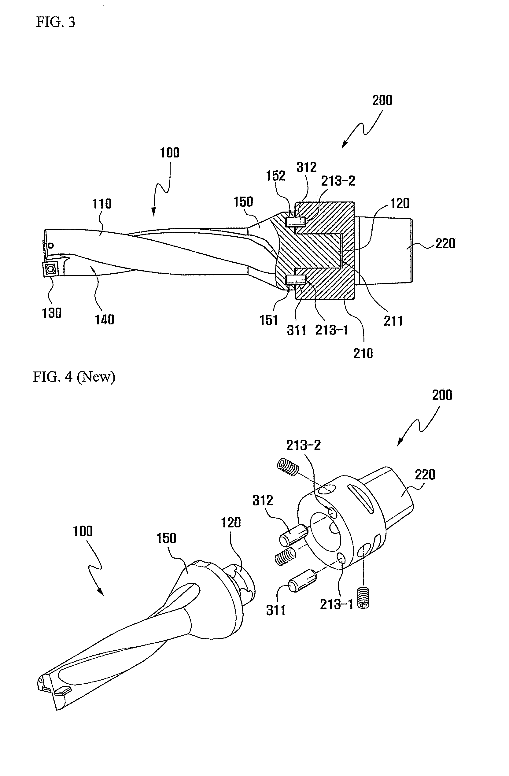
[0029]The tool 100 includes a head 110 contacted with a work-piece and a rear protrusion section 120 extended from a rear end of the head and formed integrally with the head 110. At least one cutting insert 130 is mounted to a front end of the head 110 for machining a work-piece, and a chip groove 140 is formed on an outer circumference surface of the head 110 for receiving a chip generated when the working piece is machined.

[0030]Chip is guided and moved along the chip groove 140, the chip groove 140 performing such function is formed in a spiral shape through the enti...


PUM

PropertyMeasurementUnit
circumferenceaaaaaaaaaa
torqueaaaaaaaaaa
shapeaaaaaaaaaa

Abstract

The present invention discloses a tool assembly being capable of reducing considerably an axial length of a working member (tool), in particular, a length of a male spigot to be coupled with a coupling member and transmitting a torque to a working member without generating a loss by means of a secure coupling between a male spigot of a working member (tool) having a short length and a coupling member. A tool assembly according to the present invention comprises a tool including a head to be approached to a work-piece, a male spigot extended from a rear end of the head and a flange formed at a border portion between the head and the male spigot and having a ring shaped flat rear surface; and a coupling member consisting of a first section having a cavity formed on a central portion of a front side thereof for receiving the male spigot and a second section formed at a rear side of the first section and connected to a driving means. The male spigot has a tapered surface formed on a side thereof, a through hole communicated with the cavity is formed on a side of the first section of the coupling member, and an end of a coupling screw coupled with the through holes is capable of pressurizing the tapered surface of the male spigot received in the cavity.

Description

[0001]This application claims the benefit of the filing date of Korean Patent Application No. 10-2007-0044995 filed on May 9, 2007, in the Korean Intellectual Property Office, the disclosure of which is incorporated herein in its entirety by reference.BACKGROUND OF THE INVENTION[0002]1. Field of the Invention[0003]The present invention relates a tool assembly, more particularly, to a tool assembly in which a working member is securely coupled with a coupling member and a torque can be transmitted to a working member without a loss.[0004]2. Description of the Related Art[0005]In general, a cutting tool is used in the field of cutting machining such as drilling, milling, and turning. Within the fields of drilling and milling, a tool having a rotary character is useful for machining a fixed and movable workpiece, and a tool for turning machining is fixed and has the purpose of machining work-piece which is rotating.[0006]Conventionally, a drilling tool is divided into a coupling member...

Claims


Application Information

Patent Timeline
Patent Type & Authority Patents(United States)
IPC IPC(8): B23C5/00B23B31/107
CPCB23B31/1075B23B51/048B23B2251/02Y10T279/17821Y10T408/888Y10T409/30952Y10T408/957B23B51/00B23C5/26B23B51/12
Inventor BAE, BYUNG GYUN
Owner TAEGUTEC
Why Eureka
Try Eureka