Double screw lift

A lift and screw technology, applied in the field of lifts, can solve the problems of doubts about the transmission load, material falling and hurting people, wire rope breakage, etc., so as to reduce the difficulty of handling and the limitation of installation space, reduce the difficulty and cost of production, and avoid suffering. Effect of Radial Force

Inactive Publication Date: 2019-05-03
HIWIN TECH
View PDF7 Cites 0 Cited by
  • Summary
  • Abstract
  • Description
  • Claims
  • Application Information

AI Technical Summary

Problems solved by technology

There are many kinds of transmission methods for the existing lifting devices, such as hydraulic transmission, cable transmission, screw transmission, etc. Among them, the cable transmission is the most common, but its biggest hazard is the accidental breakage of the cable, causing people to fall to death, or Accidents such as material falling and hurting people, and steel cables have the disadvantages of frequent replacement and maintenance and complicated maintenance; in addition, hydraulic transmission has leakage and follow-up maintenance problems: for example, oil pressure leakage not only causes oil pollution and pollutes the environment, but also has considerable maintenance costs. In addition, oil pipes and actuator oils have aging problems and need to be repaired and replaced regularly, so there is a tendency to use screw drive.
The above-mentioned lifting device is driven by a parallel double transmission screw. Although the required working length of the transmission screw can be shortened, it uses a telescopic tube assembly to socket the transmission screw, and the second transmission mechanism also sleeves the sleeve on the telescopic The tube assembly makes it difficult to install and adjust due to too many sets, and there are doubts about the transmission load. Moreover, the transmission screw is the main force-bearing component, so the above-mentioned transmission mechanism cannot bear the radial force

Method used


Image

  • Double screw lift
  • Double screw lift
  • Double screw lift

Examples


Embodiment Construction

[0027] Before the present invention is described in detail, it should be noted that in the following description, similar elements are denoted by the same numerals.

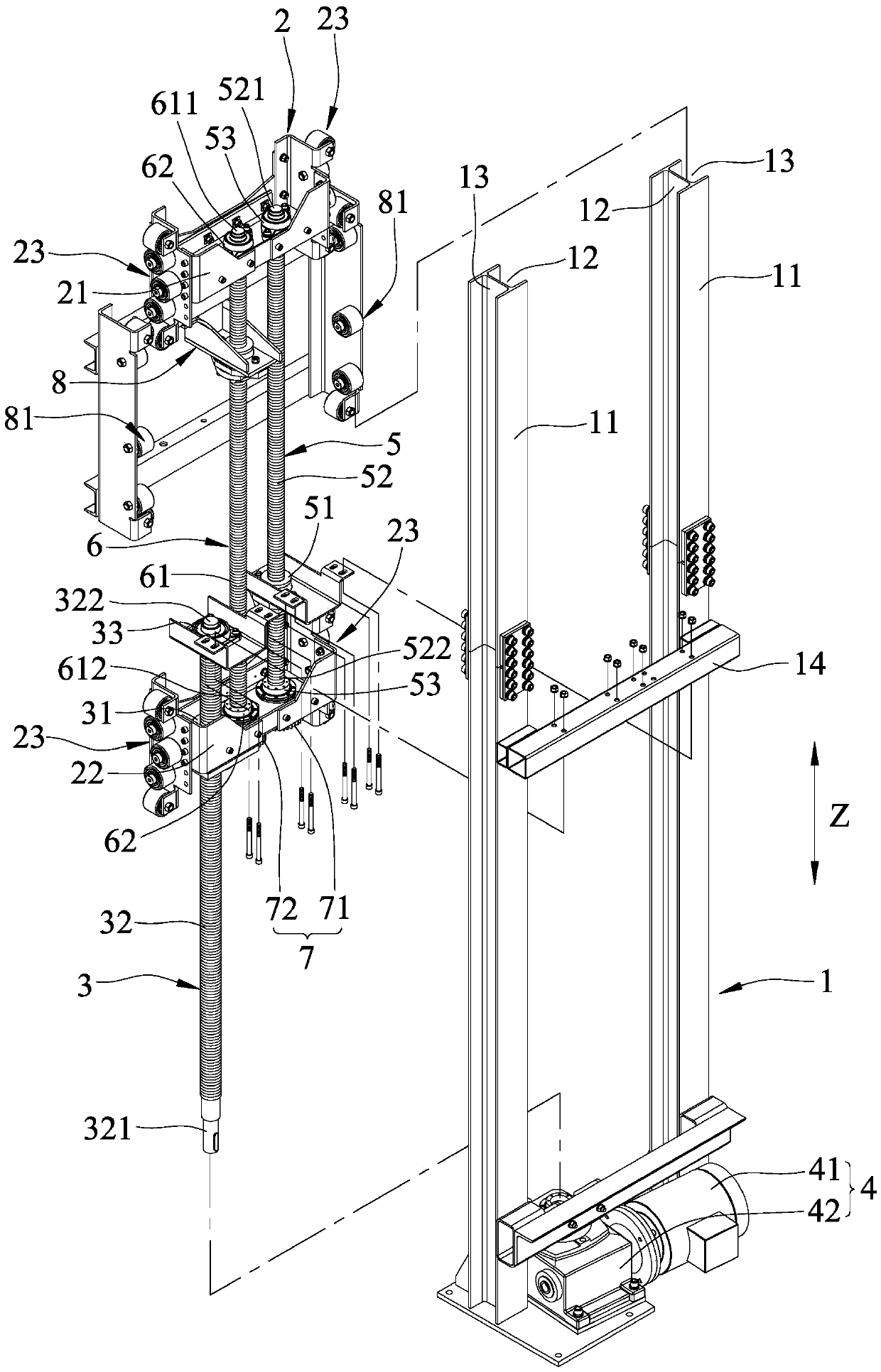
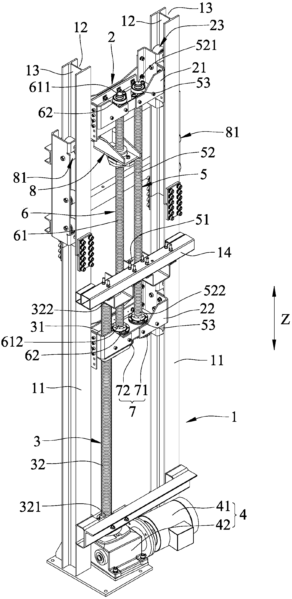
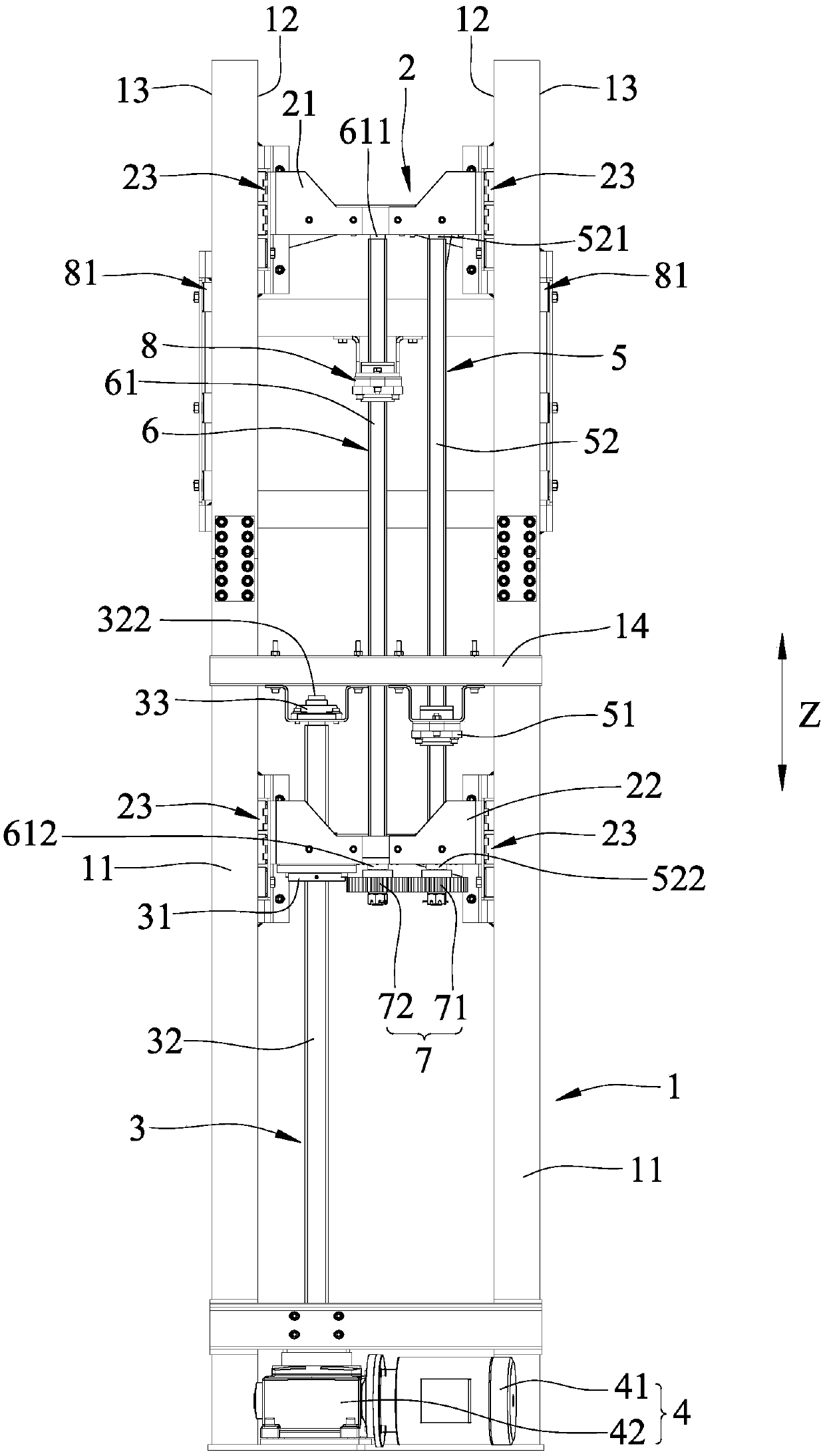
[0028] refer to figure 1 , figure 2 and image 3 , an embodiment of the screw double lift type elevator of the present invention comprises a track frame 1, a slide unit 2, a transmission screw group 3, a drive unit 4, a linkage screw group 5, a driven screw group 6. A transmission unit 7 and a load slide 8.

[0029] The track rack 1 includes two parallel and spaced apart supports 11 extending upright along an up-down direction Z, two inner rails 12 respectively arranged on opposite sides of the supports 11, two inner rails 12 respectively arranged on the opposite sides of the supports 11, The outer rail 13 at the opposite side of the support member 11, and a fixing member 14 connected to the middle section of the support member 11. Each inner rail 12 and each outer rail 13 extend along the vertical direction...


PUM


Abstract

A screw time ascending type elevator comprises a rail rack, a sliding seat unit arranged on the rail rack in a sliding manner, a transmission screw set, a driving screw set, a driven screw set, a driving unit, a transmission unit and a load sliding seat. The transmission screw set comprises a transmission nut part fixedly arranged on the sliding seat unit and a transmission screw in screwed jointwith the transmission nut part. The driving unit is used for driving the transmission screw to rotate. The driving screw set comprises a driving nut part fixedly arranged on the rail rack and a driving screw in screwed joint with the driving nut part. The driven screw set comprises a driven screw. The transmission screw, the driving screw and the driven screw are all rotationally connected with the sliding seat unit. The transmission unit is used for enabling the driving screw and the driven screw to rotate at the same time. The load sliding seat is arranged on the rail rack and connected withthe driven screw.

Description

technical field [0001] The invention relates to a lift, in particular to a screw double lift type lift. Background technique [0002] Due to the changes in the social environment, there are many high-rise buildings, people use the lifting device more and more frequently, and the degree of dependence is relatively doubled, so the safety of the lifting device cannot be ignored. There are many kinds of transmission methods for the existing lifting devices, such as hydraulic transmission, cable transmission, screw transmission, etc. Among them, the cable transmission is the most common, but its biggest hazard is the accidental breakage of the cable, causing people to fall to death, or Accidents such as material falling and hurting people, and steel cables have the disadvantages of frequent replacement and maintenance and complicated maintenance; in addition, hydraulic transmission has leakage and follow-up maintenance problems: for example, oil pressure leakage not only causes o...

Claims


Application Information

Patent Timeline
Patent Type & Authority Patents(China)
IPC IPC(8): B66B9/00B66B11/04
CPCB66B9/00B66B11/04
Inventor 王福清蔡千祥王中佑张耀仁林宗颍
Owner HIWIN TECH
Why Eureka
Try Eureka