Automobile, engine, crank linkage mechanism and its connecting rod assembly
A connecting rod assembly, engine technology, applied in the engine, crank connecting rod mechanism and its connecting rod assembly, automobile field, can solve the problem that the engine compression ratio cannot be too large, etc.
- Summary
- Abstract
- Description
- Claims
- Application Information
AI Technical Summary
Problems solved by technology
Method used
Image
Examples
no. 1 example
[0104] An automobile engine includes a crank linkage, which includes an engine crankshaft and a connecting rod assembly.
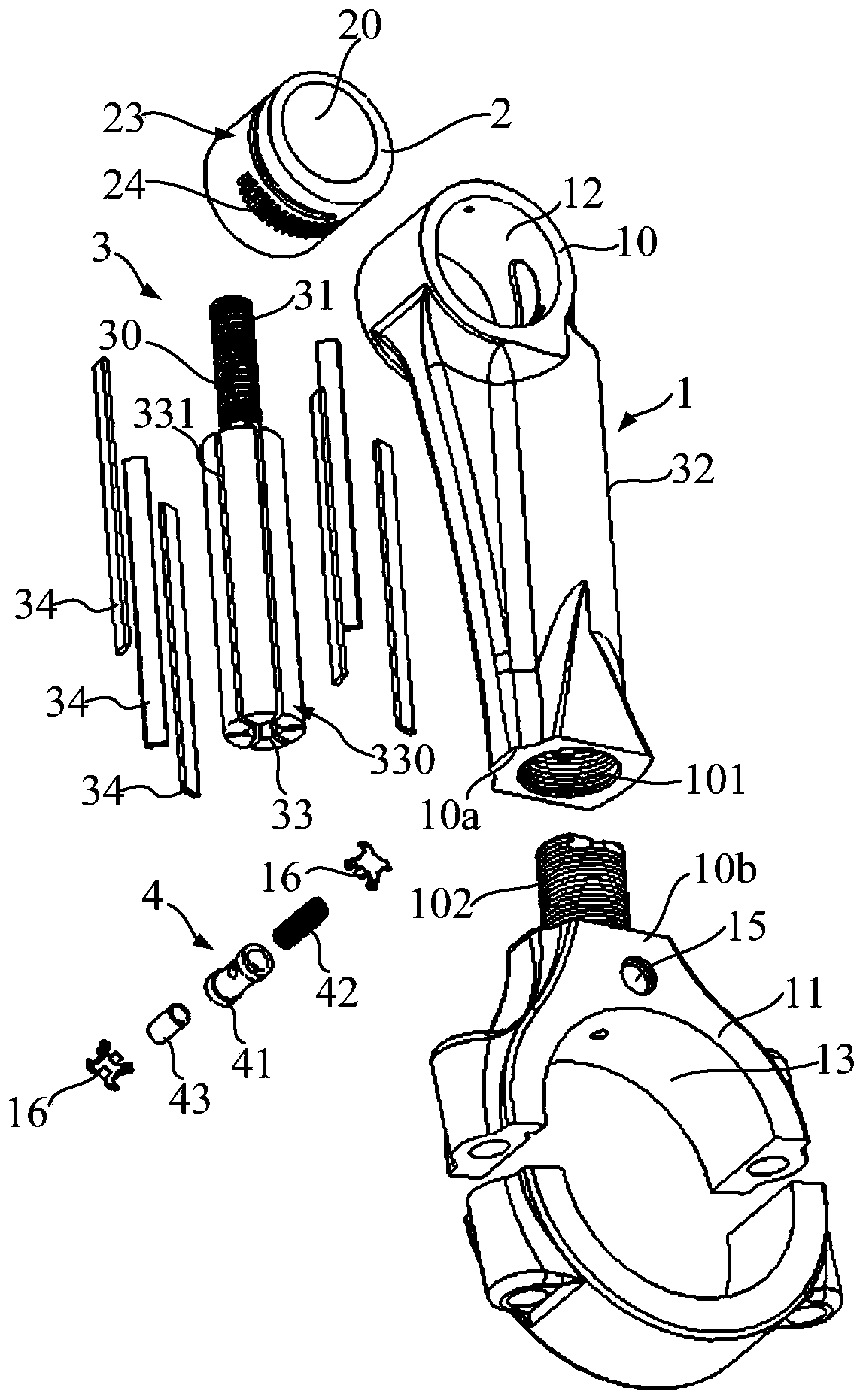
[0105] refer to figure 1, The connecting rod assembly includes: a connecting rod 1 , an eccentric sleeve 2 with an eccentric hole 20 and a hydraulic driver 3 with an output shaft 30 . The connecting rod 1 has a connecting rod small end 10 and a connecting rod large end 11. The connecting rod small end 10 is used to extend into the piston in the engine cylinder and connects the piston (not shown in the figure), and the connecting rod large end 11 is used to cover the engine. The connecting rod journal of the crankshaft is connected to the engine crankshaft.
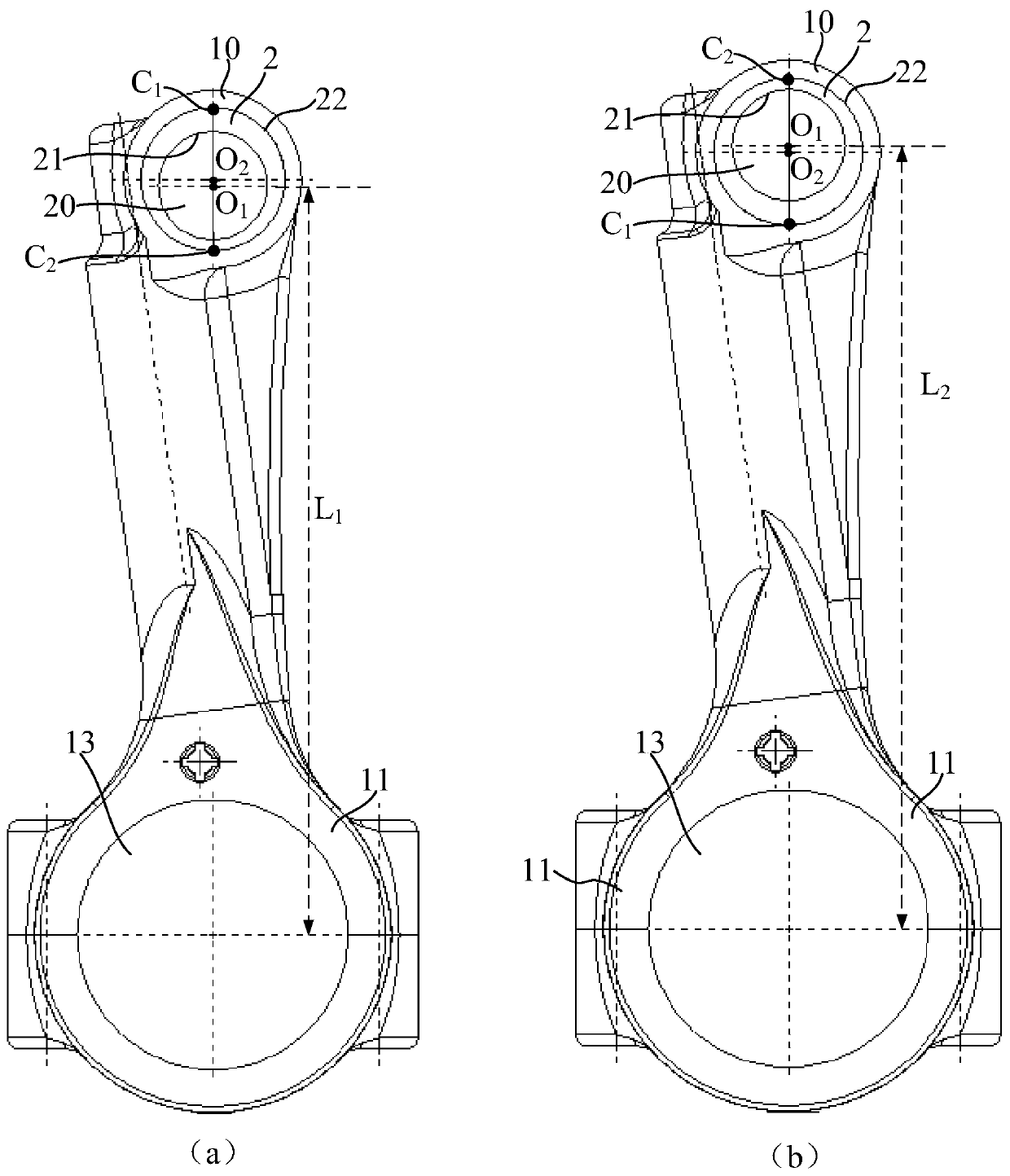
[0106] combine figure 2 , The connecting rod big end 11 has a connecting rod big end hole 13 . The small head 10 of the connecting rod is provided with an eccentric sleeve installation hole 12 to accommodate the eccentric sleeve 2 . The inner circle 21 of the eccentric sleeve 2 is not concentric w...
no. 2 example
[0180] Compared with the first embodiment, the second embodiment differs in that:
[0181] refer to Figure 20 and Figure 21 , the first part 10a' of the connecting rod 1' is provided with an external threaded part 103 and the second part 10b' is provided with an internal threaded part 104. Rotor cavity 50 (combined with Figure 22 ) is located in the second part 10b' and communicates axially with the internal threaded part 104. After assembly, the external threaded part 103 can seal the rotor cavity 50 to prevent the hydraulic oil in the rotor cavity 50 from flowing out from the internal threaded part 104. The external thread portion 103 is provided with an output shaft receiving hole 105, and the output shaft 30' of the hydraulic driver (not shown in the figure) (combined with Figure 23 ) can pass between the output shaft receiving hole 105 and the outer circular surface of the eccentric sleeve (not shown in the figure) for worm gear transmission.
[0182] refer to F...
no. 3 example
[0191] Compared with the first embodiment and the second embodiment, the difference of the third embodiment is:
[0192] refer to Figure 24 and Figure 25 , The connecting rod 6 is integrally formed, and the connecting rod 6 is provided with a connecting rod cavity 60, and a hydraulic driver (not shown in the figure) can be arranged in the connecting rod cavity 60, and the connecting rod cavity 60 can be used as a rotor cavity. The connecting rod cavity 60 has an assembly inlet 62 located on the inner circular surface 61 of the big head, and a big head cover 63 is arranged in the assembly inlet 62, and the big head cover 63 plays a role of isolating and sealing the driving chambers of the hydraulic driver.
[0193] The big head cover part 63 has an end face 630 for facing the crankshaft of the engine. The end face 630 is an arc surface, which may have the same radius as the inner circular face 61 of the big head, and the two may be flush with each other.
[0194] combine ...
PUM
 Abstract
Description
Claims
Application Information
 - R&D
- Intellectual Property
- Life Sciences
- Materials
- Tech Scout
- Unparalleled Data Quality
- Higher Quality Content
- 60% Fewer Hallucinations
Browse by: Latest US Patents, China's latest patents, Technical Efficacy Thesaurus, Application Domain, Technology Topic, Popular Technical Reports.
© 2025 PatSnap. All rights reserved.Legal|Privacy policy|Modern Slavery Act Transparency Statement|Sitemap|About US| Contact US: help@patsnap.com


