Indoor ventilation equipment capable of controlling ventilation quantity

A technology of ventilation equipment and ventilation volume, which is applied in ventilation systems, mechanical equipment, lighting and heating equipment, etc., can solve the problems such as the inability to effectively improve the absorption range of the pipe entrance, and the adsorption capacity to increase the effective dust collection area, so as to avoid poor ventilation effect. The effect of improving the ventilation effect and reducing the working length

Active Publication Date: 2021-12-17
桃源县漆河镇中学
View PDF14 Cites 0 Cited by
  • Summary
  • Abstract
  • Description
  • Claims
  • Application Information

AI Technical Summary

Problems solved by technology

[0003]The object of the present invention is to provide a kind of indoor ventilation equipment with controllable ventilation volume, to solve the problem that the inlet position of the pipeline proposed in the above background technology is fixed, resulting in adsorption The increase of the capacity is not proportional to the increase of the effective dust collection area, that is, the adsorption force increases to a certain strength and cannot effectively improve the absorption range of the pipeline inlet

Method used


Image

  • Indoor ventilation equipment capable of controlling ventilation quantity
  • Indoor ventilation equipment capable of controlling ventilation quantity
  • Indoor ventilation equipment capable of controlling ventilation quantity

Examples


Embodiment 1

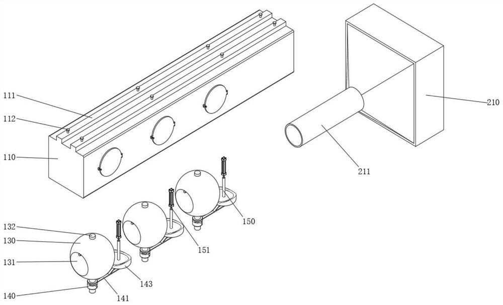
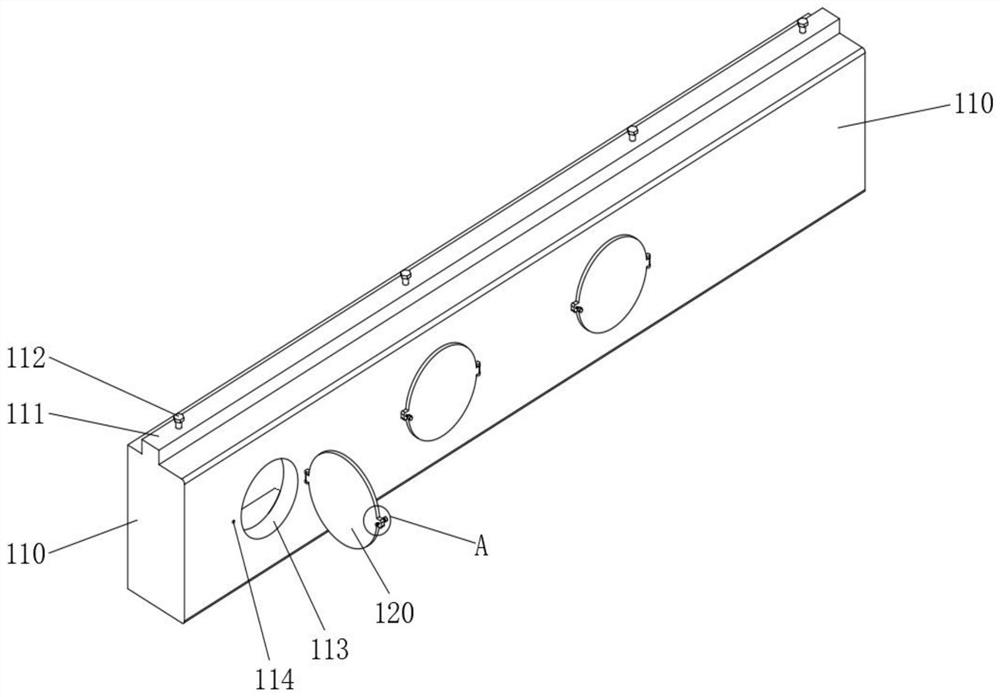
[0050] see Figure 1-Figure 11As shown, an indoor ventilation device with controllable ventilation volume is provided, including an indoor unit 100 and an outdoor unit 200 outside the indoor unit 100, and the indoor unit 100 at least includes:

[0051] Air duct 110, the inner channel of air duct 110 is circular, and there are multiple inlets 115 below the air duct 110, and baffles 118 are arranged on the inlets 115 to limit the range of motion of the bottom cover 143, and a bottom cover is provided in the inlet 115 143, a straight rod 150 is arranged above the bottom cover 143, an electric push rod 151 is arranged above the straight rod 150, and the electric push rod 151 is fixed in the air duct 110, and the movable shaft of the electric push rod 151 is fixedly connected with the straight rod 150, and the air duct The tail end of 110 is provided with connection port 116;

[0052] A ball 130, a through hole 131 is opened on the ball 130, a rotating shaft 132 is arranged on the...


PUM


Abstract

The invention relates to indoor ventilation equipment, in particular to indoor ventilation equipment capable of controlling ventilation quantity. The indoor ventilation equipment comprises an air duct, an inner channel of the air duct is circular, a plurality of inlets are formed below the air duct, baffles are arranged on the inlets, bottom covers are arranged in the inlets, straight rods are arranged above the bottom covers, electric push rods are arranged above the straight rods, the electric push rods are fixed in the air duct, movable shafts of the electric push rods are fixedly connected with the straight rods, through holes are formed in round balls, and rotating shafts are arranged on the upper portions and the lower portions of the round balls; and the multiple balls are located behind the multiple inlets, and transmission structures are connected with the rotating shafts and the bottom covers and used for driving the multiple balls to rotate. According to the indoor ventilation equipment, the opening states of the multiple inlets are controlled through the arranged electric push rods, specifically, the multiple inlets are sequentially opened along with the increase of the rotating speed of a fan, and the inlets in different positions have different effective ventilation ranges, so that the indoor ventilation efficiency is improved on the whole, and meanwhile, the problem that the ventilation effect is poor due to the fact that a ventilation pipeline is too long is solved.

Description

technical field [0001] The invention relates to an indoor ventilation device, in particular to an indoor ventilation device with a controllable ventilation rate. Background technique [0002] Indoor ventilation equipment can discharge the indoor air. For some manufacturers, the use of indoor ventilation equipment can effectively reduce the indoor dust content. In order to save electricity, different air dust content uses different motor speeds. This method increases the motor speed. Finally, the speed of the fan increases and the suction force from the ventilation duct increases, but the position of the entrance of the duct is fixed, resulting in an increase in the adsorption capacity that is not proportional to the increase in the effective dust collection area, that is, the adsorption force cannot be effectively increased to a certain strength. The absorption range of the entrance of the pipeline is improved. In view of this, the present invention proposes an indoor ventil...

Claims


Application Information

Patent Timeline
IPC IPC(8): F24F7/003F24F7/06F24F8/108F24F13/06
CPCF24F7/003F24F7/06F24F8/108F24F13/06Y02B30/70
Inventor 刘永光
Owner 桃源县漆河镇中学
Why Eureka
Try Eureka