Self-cooling fan

A self-cooling and fan technology, applied in the direction of mechanical equipment, machines/engines, liquid fuel engines, etc., can solve the problems of limited operating area, reduced user work efficiency, and increased work tasks, so as to increase the sweeping area and facilitate gas Inflow, avoid the effect of poor ventilation

Pending Publication Date: 2022-04-15
郭旭旭
View PDF0 Cites 0 Cited by
  • Summary
  • Abstract
  • Description
  • Claims
  • Application Information

AI Technical Summary

Problems solved by technology

[0003] In the existing fan, the exhaust outlet of the fan is fixed, and the exhausted air can only be discharged in one direction, and the effective area is limited. If the working direction needs to be changed, the main body of the fan needs to be moved continuously, which reduces the inconvenience for the user. The user's work efficiency and work tasks have also increased

Method used


Image

  • Self-cooling fan
  • Self-cooling fan
  • Self-cooling fan

Examples


Embodiment approach

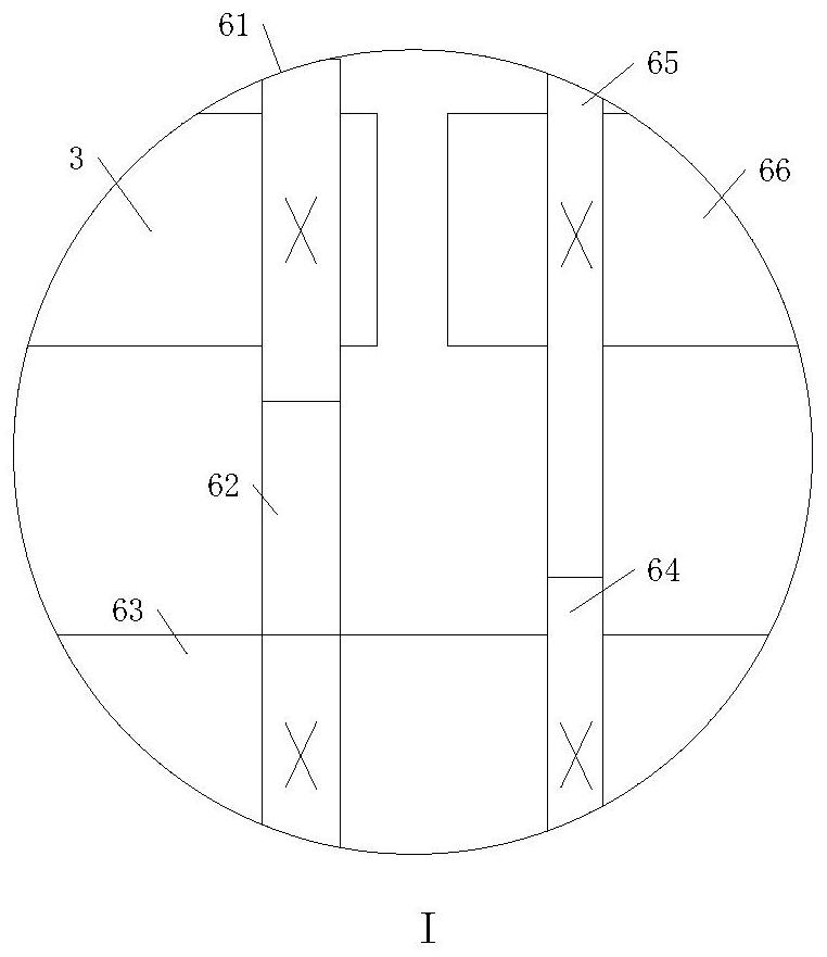
[0028] As an embodiment of the present invention, the reduction device 6 includes: A small gear 61, A large gear 62, reduction shaft 63, B small gear 64, B large gear 65 and output shaft 66, the A small gear 61 Fixedly installed on the rotating main shaft 3, the A large gear 62 is fixedly installed on the left side of the reduction shaft 63 and constitutes a gear transmission with the A small gear 61, and the two ends of the reduction shaft 63 are rotatably connected with the heat shield 18. The B small gear 64 is fixedly installed on the right side of the reduction shaft 63, the B large gear 65 is fixedly installed on the output shaft 66 and forms a gear transmission with the B small gear 64, and the left end of the output shaft 66 is in the middle of the two heat shields 18 The position is close to the right side, and the output shaft 66 is fixedly connected with the right heat shield 18 close to the middle position.

[0029] The rotating main shaft 3 rotates, driving the A ...


PUM


Abstract

The invention belongs to the technical field of self-cooling fans, and particularly relates to a self-cooling fan which comprises a fan body, a mounting box and a rotating spindle, the mounting box is fixedly connected to one side of the fan body, and the fan body comprises a swing shell, a main shell, a sliding groove, an oil inlet, a rotating groove, an air vent, an oil outlet and a heat insulation plate. The rotating main shaft penetrates through the left wall of the fan body, a driving motor is arranged in the mounting box, and the driving motor is fixedly connected with the rotating main shaft; a rotating groove is formed in the fan body, rotating fan blades are arranged in the rotating groove, the rotating main shaft penetrates through the heat insulation plate on the left side and extends to the position between the two heat insulation plates, a speed reduction device and a moving device are arranged in the fan body, the speed reduction device is connected with the rotating main shaft, and the moving device is connected with the speed reduction device. By arranging the speed reducer and the moving device, the swing shell is driven to reciprocate, the working area is increased, and therefore the working efficiency of a user is improved.

Description

technical field [0001] The invention belongs to the technical field of self-cooling fans, and in particular relates to a self-cooling fan. Background technique [0002] The fan is a machine that relies on the input mechanical energy to increase the gas pressure and discharge the gas. It is a driven fluid machine. Fans are widely used in ventilation, dust removal and cooling of factories, mines, tunnels, cooling towers, vehicles, ships and buildings, ventilation and induction of boilers and industrial furnaces, cooling and ventilation in air conditioning equipment and household appliances , Grain drying and selection, wind tunnel wind source and hovercraft inflation and propulsion, etc. [0003] In the existing fan, the exhaust outlet of the fan is fixed, and the exhausted air can only be discharged in one direction, and the effective area is limited. If the working direction needs to be changed, the main body of the fan needs to be moved continuously, which reduces the inco...

Claims


Application Information

Patent Timeline
Patent Type & Authority Applications(China)
IPC IPC(8): F04D25/10F04D29/00F04D29/40F04D29/58
CPCF04D25/10F04D29/002F04D29/403F04D25/082F04D29/5806F04D29/5853
Inventor 郭旭旭王志豪许聪
Owner 郭旭旭
Why Eureka
Try Eureka