Sputter ion pump

a sputter ion pump and ion technology, applied in the field of vacuum pumps, can solve the problems of large volume, high fabrication cost, and large volume of the conventional sputter ion pump

Active Publication Date: 2010-09-30
TSINGHUA UNIV +1
View PDF8 Cites 4 Cited by
  • Summary
  • Abstract
  • Description
  • Claims
  • Application Information

AI Technical Summary

Benefits of technology

[0033]Compared with the conventional pumps, the present sputter ion pump has the following advantages. Firstly, the primary electron emitter is a field emission device, such as a carbon nanotube and so on, and a power supply required therefor is typically only on the order of several milliwatts. This field emission device requires considerably lower power supply than a hot electron emitter. Secondly, by adopting the secondary electron emitter made of a high secondary electron emission coefficient material, such as copper (Cu) or platinum (Pt), more electrons can be injected into the discharge zone and fewer electrons can escape from this zone. This improved net flow of electrons is beneficial to the oscillation of electrons. Thirdly, the angle formed between the axially symmetric plane defined by the two anode poles and the plane defined by the center of the aperture and the central axis of the vacuum chamber can be chosen to be less than 30 degrees, thus helping to substantially reduce, if not prevent entirely, the escape of electrons out of the vacuum chamber through the aperture and from thereby bombarding the secondary electron emitter. Fourthly, because of the relatively large radius of curvature of the anode poles, the electron can spirally oscillate along the center axis of the vacuum chamber, thus preventing the electrons from tending to escape out of the aperture in the first place. Fifthly, the sputter ion pump is free of a magnetic field and has a simpler structure and a lower fabrication cost. Therefore, the present ion pump can be effectively used in high vacuum applications.

Problems solved by technology

However, the conventional sputter ion pump has a plurality of disadvantages such as a large size, a heavy weight, and a high fabrication cost.
Furthermore, a magnetic leakage may occur, and the leakage could affect any peripheral measuring apparatus (e.g., precision and so on).
However, the sputter ion pump can only perform the stable discharge process in a narrow region (i.e., in the approximate range from 10−3 to 10−6 Torr).
Furthermore, the adoption of the hot cathode electron injection results in the sputter ion pump having a complex structure for the electron emission and having a large power consumption.

Method used


Image

  • Sputter ion pump
  • Sputter ion pump
  • Sputter ion pump

Examples


Embodiment Construction

[0020]Reference will now be made to the drawings to describe embodiments of the present sputter ion pump, in detail.

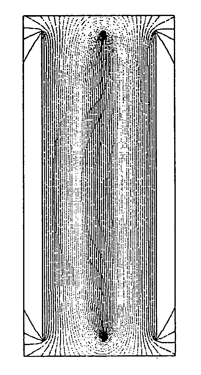
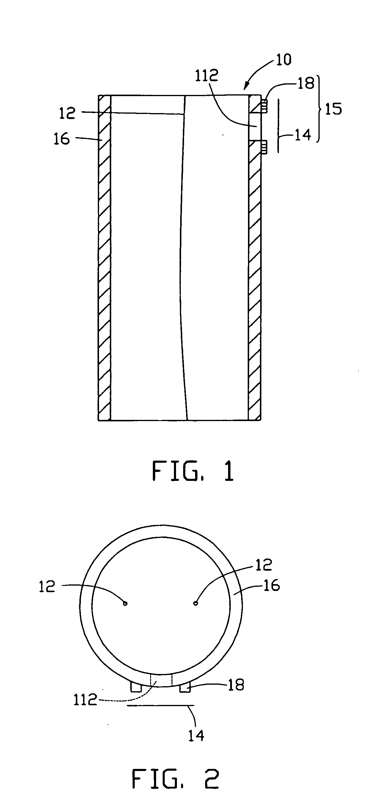
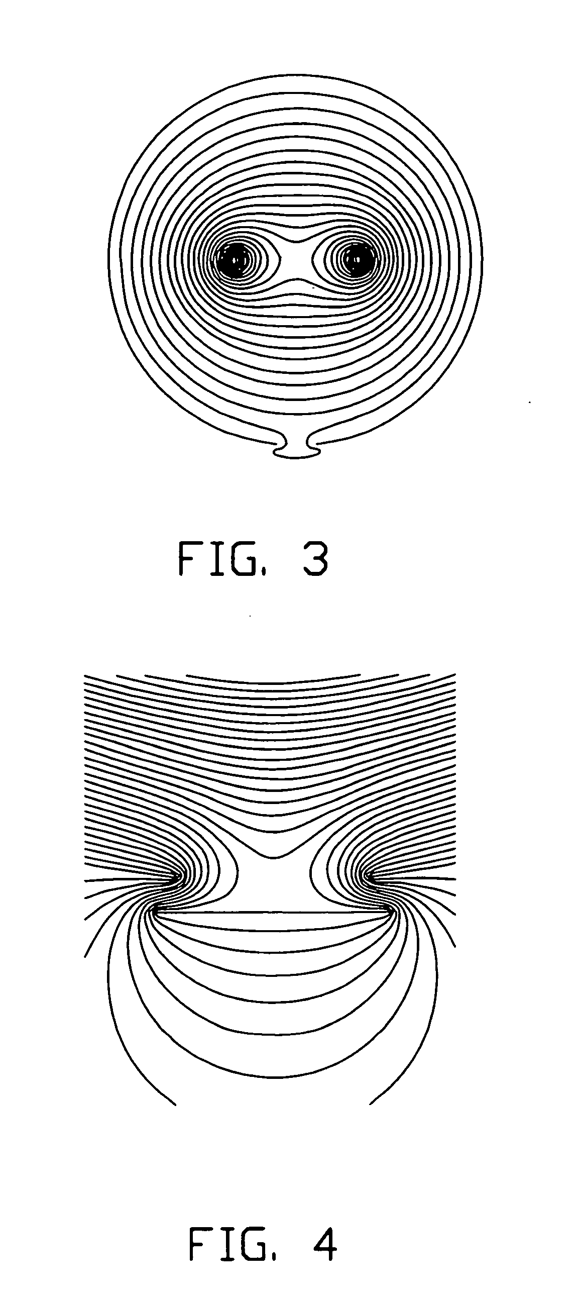
[0021]FIGS. 1 and 2 are schematic axial and radial cross-sectional views, respectively, showing a first embodiment of the present sputter ion pump 10. Referring to FIGS. 1 and 2, the sputter ion pump 10 includes a vacuum chamber 16, two parallel anode poles 12, and a cold cathode electron device 15. The vacuum chamber 16 itself acts as a cathode electrode and includes at least one aperture 112, located on an outer wall (not labeled) thereof, through which electrons can be injected. Furthermore, an electrostatic shield is applied to opposite ends (not labeled) of the vacuum chamber 16 to avoid electrons escaping therefrom.

[0022]The vacuum chamber 16 typically has a cylindraceous (i.e., cylindrical or nearly so) shape or a spherical shape. The vacuum chamber 16 is advantageously made of an oxidation-resistant metal or alloy such as a material selected from a group consis...


PUM


Abstract

A sputter ion pump includes one vacuum chamber, two parallel anode poles and one cold cathode electron emitter. The vacuum chamber includes at least one aperture located in an outer wall thereof. The two parallel anode poles are positioned in the vacuum chamber and arranged in a symmetrical configuration about a center axis of the vacuum chamber. The cold cathode electron emission device is located on or proximate the outer wall of the vacuum chamber and faces a corresponding aperture. The cold cathode electron emission device is thus configured for injecting electrons through the corresponding aperture and into the vacuum chamber. The sputter ion pump produces a saddle-shaped electrostatic field and is free of a magnetic field. The sputter ion pump has a simplified structure and a low power consumption.

Description

BACKGROUND[0001]1. Field of the Invention[0002]The present invention relates to a vacuum pump known as a sputter ion pump and, more particularly, relates to a sputter ion pump that has a saddle-shaped electrostatic field and that is free of magnetic field.[0003]2. Discussion of Related Art[0004]A sputter ion pump is a kind of vacuum pump. A conventional sputter ion pump generally includes a cathode and anode electrode, with a high voltage applied therebetween. Electrons spirally move in a high magnetic field and collide with gas molecules. This collision ionizes the gas molecules. The cathode electrode is subjected to a sputtering process by means of the ionized gas molecules activating the surfaces thereof. The ionized gas molecules are absorbed on and / or embedded in the active surfaces of the cathode electrode; and / or are caught by the surfaces of the anode electrode, thereby performing an evacuation of gases. However, the conventional sputter ion pump has a plurality of disadvant...

Claims


Application Information

Patent Timeline
Patent Type & Authority Applications(United States)
IPC IPC(8): H01J41/18
CPCF04B37/02H01J41/20F04B37/14
Inventor QIAN, LITANG, JIELIU, LIANGQI, JINGCHEN, PI-JINHU, ZHAO-FUFAN, SHOU-SHAN
Owner TSINGHUA UNIV
Why Eureka
Try Eureka