Lithium-ion battery

a lithium-ion battery and lithium-ion technology, applied in the field of lithium-ion batteries, can solve the problems that the polyaniline layer cannot be directly contacted, affect the normal charging performance of the battery, etc., and achieve the effects of enhancing the electrical conductivity of the polyaniline layer and the polyphenyl layer, discharging excess electricity, and reducing the voltage of the battery

Inactive Publication Date: 2015-03-26
NINGDE AMPEREX TECH
View PDF4 Cites 3 Cited by
  • Summary
  • Abstract
  • Description
  • Claims
  • Application Information

AI Technical Summary

Benefits of technology

[0016]The invention has the beneficial effects that: when the battery is charged to the oxidation potentials of the polyaniline layer and the polyphenyl layer, the electronic conductivities of the polyaniline layer and the polyphenyl layer are enhanced, and a controllable internal short circuit occurs via contact between the polyaniline layer and the polyphenyl layer, thus discharging excess electricity, such that the battery is under a safe state. After the

Problems solved by technology

The polyaniline layer cannot be directly contacted with a cathode material since the oxidat

Method used


Image

  • Lithium-ion battery
  • Lithium-ion battery
  • Lithium-ion battery

Examples


embodiment 1

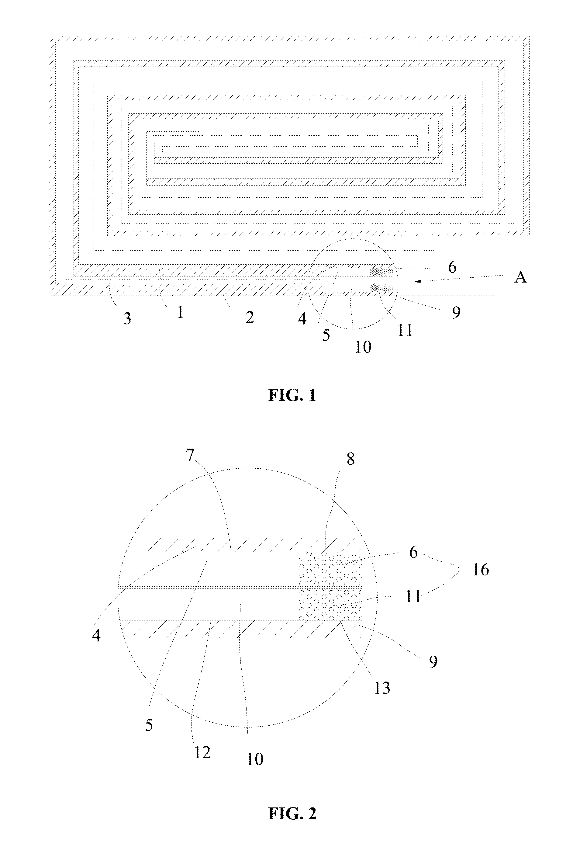
[0026]As illustrated in FIG. 1 and FIG. 2, a lithium-ion battery comprises an anode plate 1, a cathode plate 2, a separator 3 and electrolyte, wherein the separator 3 is arranged between the anode plate 1 and the cathode plate 2. The anode plate 1 comprises an anode current collector 4 and an anode active material layer 5. The anode current collector 4 is provided with an anode coating area 7 and an anode blank area 8, and the anode active material layer 5 is coated in the anode coating area 7. The cathode plate 2 comprises a cathode current collector 9 and a cathode active material layer 10. The cathode current collector 9 is provided with a cathode coating area 12 and a cathode blank area 13, and the cathode active material layer 10 is coated in the cathode coating area 12. When both the anode blank area 8 and the cathode blank area 13 are coated with a polymer layer 16, the two polymer layers 16 are mutually contacted.

[0027]A polyaniline layer 6 or a polyphenyl layer 11 is config...

embodiment 2

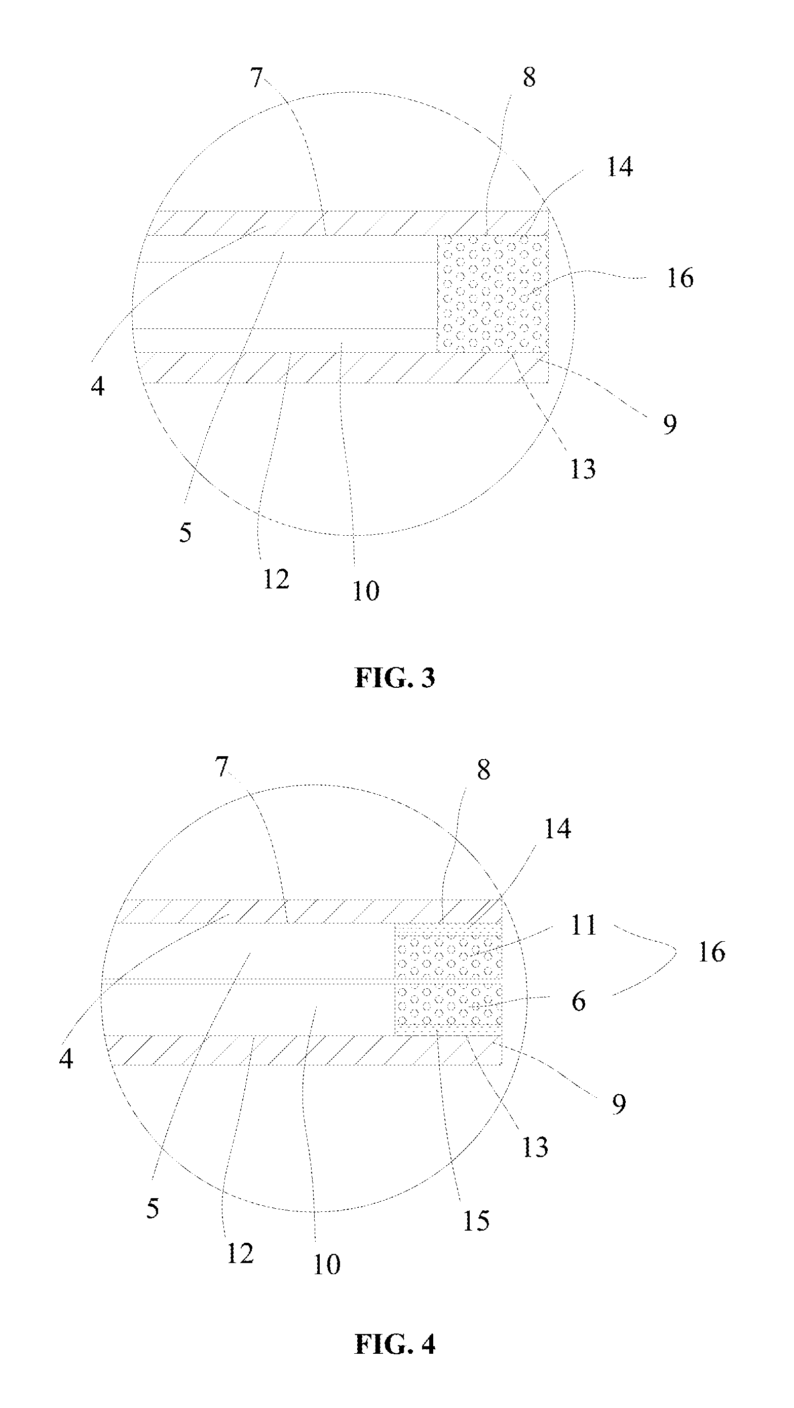
[0028]As illustrated in FIG. 3, embodiment 2 differs from embodiment 1 in that: a polyphenyl layer 11 of this embodiment is coated on an anode blank area 8; moreover, a first intermediate layer 14 is arranged between the polyphenyl layer 11 and the anode blank area 8 of the embodiment. A polyaniline layer 6 is coated on a cathode blank area 13. The polyaniline layer 6 is contacted with the polyphenyl layer 11. A potential when arranging the first intermediate layer 14 is more stable than a potential when being directly coated on an anode current collector 4. Therefore, excess electricity can be discharged quickly, such that safety of overcharging is improved. Generally, a material of the first intermediate layer 14 is the same as a material of an anode active material layer 5.

[0029]Other structures are the same as the structures of embodiment 1, which are thus not described herein any further.

embodiment 3

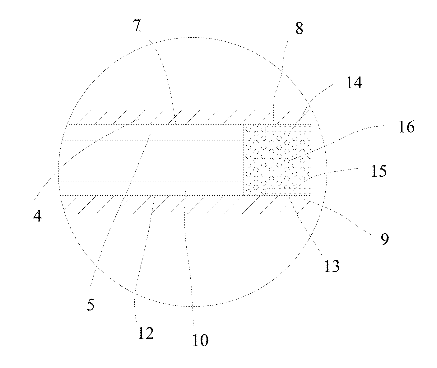
[0030]As illustrated in FIG. 4, embodiment 3 differs from embodiment 2 in that: a second intermediate layer 15 is arranged between a polyaniline layer 6 and a cathode blank area 13 of the embodiment. Thickness sum of a polyphenyl layer 11 and a first intermediate layer 14 is no more than thickness of an anode active material layer 5, and thickness sum of the polyaniline layer 6 and the second intermediate layer 15 is no more than thickness of a cathode active material layer 10, thus being beneficial for improving energy density of the battery. Moreover, an effect of discharge is better than that of embodiment 2.

[0031]Other structures are the same as the structures of embodiment 2, which are thus not described herein any further.


PUM


Abstract

A lithium-ion battery, comprises an anode plate, a cathode plate, a separator and electrolyte, wherein the separator is arranged between the anode plate and the cathode plate. The anode plate comprises an anode current collector and an anode active material layer. The anode current collector is provided with an anode coating area and an anode blank area, and the anode active material layer is coated on the anode coating area. The cathode plate comprises a cathode current collector and a cathode active material layer. The cathode current collector is provided with a cathode coating area and a cathode blank area, and the cathode active material layer is coated on the cathode coating area. When both the anode blank area and the cathode blank area are coated with a polymer layer, the two polymer layers are mutually contacted.

Description

FIELD OF THE INVENTION[0001]The invention belongs to the field of battery technologies, and relates to a lithium-ion battery particularly.BACKGROUND OF THE INVENTION[0002]Lithium-ion batteries have the advantages of higher energy density and long cycle life when in comparison with lead-acid batteries, nickel-metal hydride batteries and nickel-cadmium batteries, and have been broadly applied to the field of consumer electronics at present.[0003]Side reactions inside lithium ions and the safety performance of the batteries while overcharging are related to voltages of the batteries usually. On one hand, when voltages of the batteries are higher, the side reactions inside the batteries are more and performance attenuation of the batteries is more obvious. On the other hand, the safety performance of the batteries while overcharging is also related to the voltages of the batteries. The voltages are raised faster during overcharging, which will easily cause a safety problem to the batter...

Claims


Application Information

Patent Timeline
IPC IPC(8): H01M4/62H01M10/42H01M10/0525
CPCH01M4/628H01M10/4235H01M10/0525H01M10/058H01M10/0587H01M2200/00Y02E60/10Y02P70/50
Inventor WANG, XIAOMEIFU, CHENGHUAHAN, CHANGLONGCHU, CHUNBO
Owner NINGDE AMPEREX TECH
Why Eureka
Try Eureka