Method of testing bit error rates for a wavelength division multiplexed optical communication system

Inactive Publication Date: 2009-04-21
CIENA
View PDF20 Cites 17 Cited by
  • Summary
  • Abstract
  • Description
  • Claims
  • Application Information

AI Technical Summary

Benefits of technology

[0019]It is an object of the present invention to provide a quick method of determining whether the BER is acceptable.
[0020]It is another object of the present invention to provide an inexpe

Problems solved by technology

However, there is a problem in testing a WDM optical communication system having many optical communication channels, each operating with a low specified

Method used


Image

  • Method of testing bit error rates for a wavelength division multiplexed optical communication system
  • Method of testing bit error rates for a wavelength division multiplexed optical communication system
  • Method of testing bit error rates for a wavelength division multiplexed optical communication system

Examples


Example

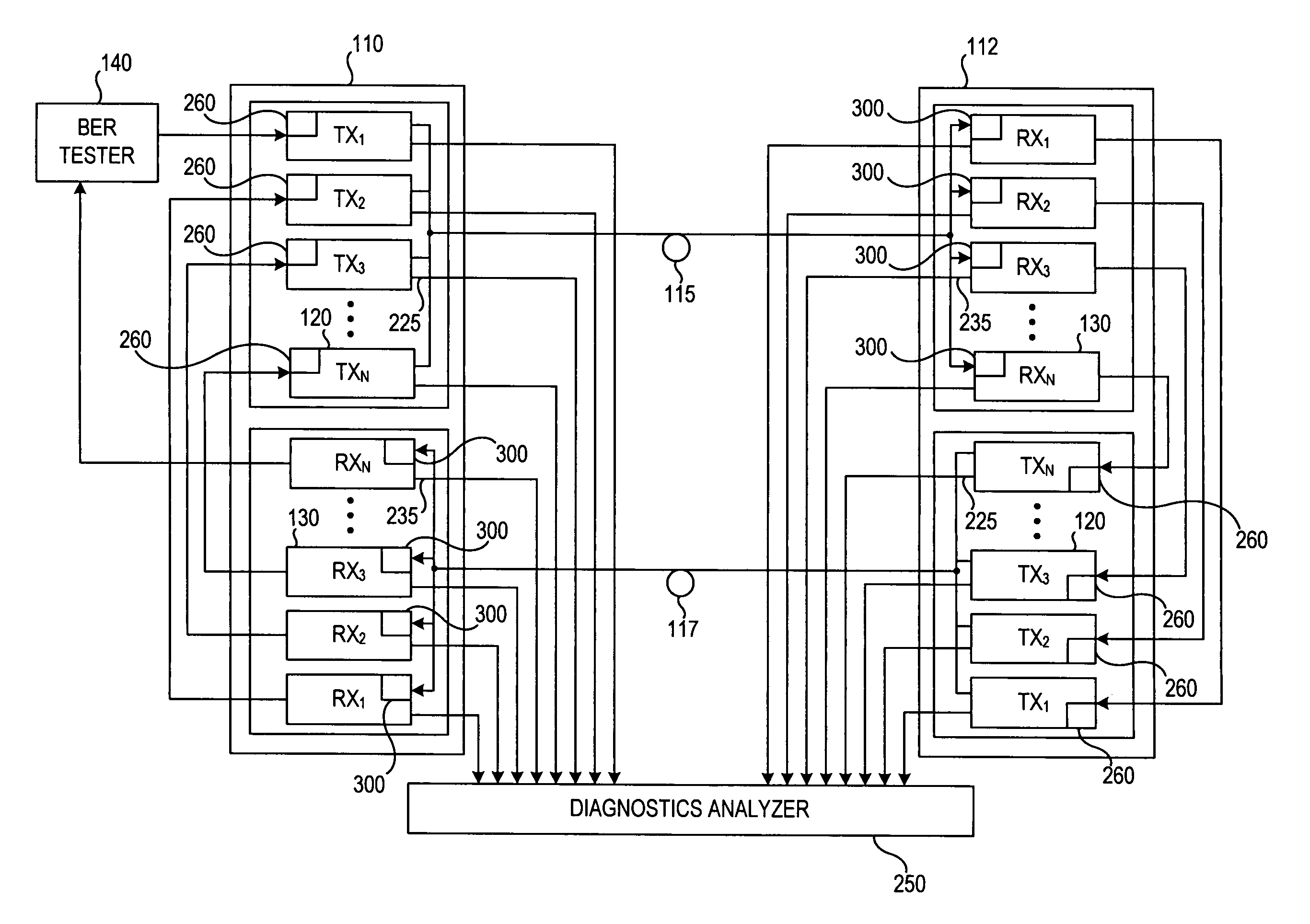
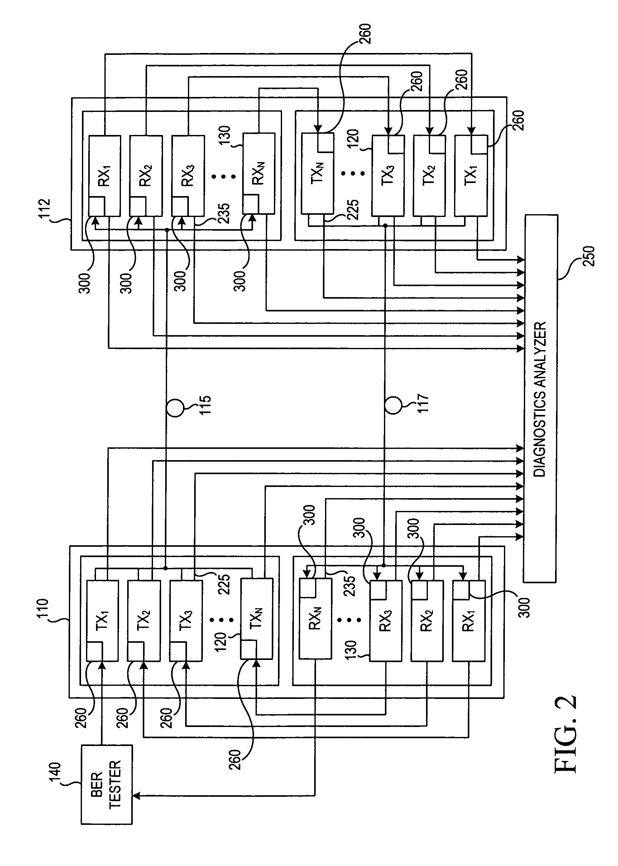
[0030]A preferred arrangement for testing the BER for optical communication channels in a WDM optical communication system is shown in FIG. 2.

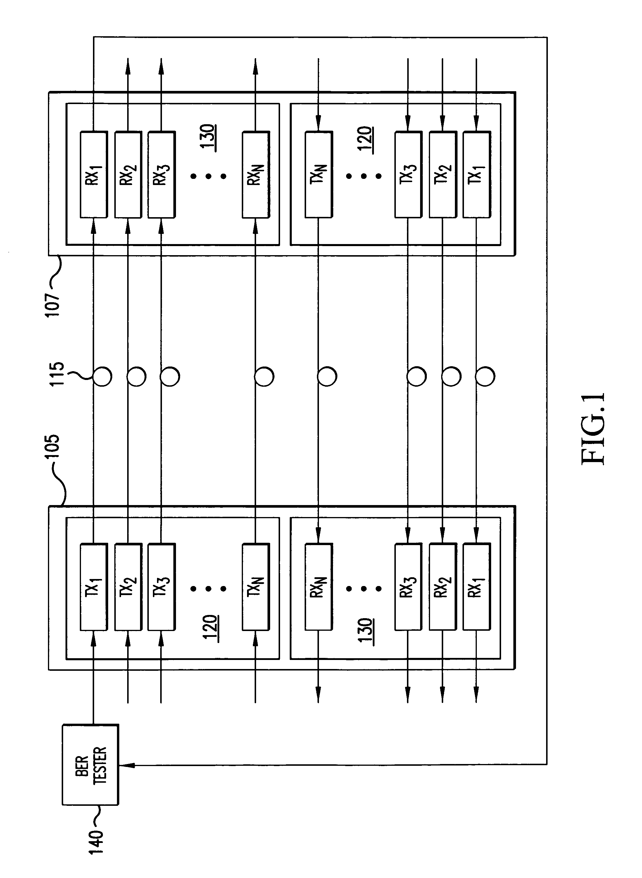
[0031]The WDM optical communication system shown in FIG. 2 comprises two optical communication network elements 110,112 each comprising a plurality of optical transmitters 120 and optical receivers 130. In a preferred embodiment, each of the optical communication network elements 110,112 comprises N optical transmitters 120 and N optical receivers which communicate data over N forward optical communication channels, from the first optical communication network element 110 to the second optical communication network element 112, and N return optical communication channels, from the second optical communication network element 112 back to the first optical communication network element 110, on a pair of optical fibers 115,117 respectively.

[0032]A single BER tester 140 is used to test BER for the optical communication system. The BER tester 140 c...


PUM


Abstract

In a wavelength division multiplexed (WDM) optical communication system having optical transmitters and receivers communicating via a optical channels, the bit error rate (BER) for the optical channels is tested simultaneously by performing a BER measurement for the cascaded chain. A BER test signal is supplied from a BER tester to a first optical transmitter. The BER test signal passes through the optical channels. The last optical receiver in the cascaded chain supplies the test signal to the BER tester measure the BER. The measured BER is compared to a predetermined system BER threshold to determine if the optical channels meet their specified BER values. Each optical transmitter and receiver includes a performance monitoring circuit that monitors the quality of the BER signal supplied to the optical transmitter/receiver for identifying one or more optical channels that the measured BER exceeds a predetermined system BER threshold.

Description

BACKGROUND OF THE INVENTION[0001]1) Field of the Invention[0002]This invention pertains to the field of wavelength division multiplexed optical communication systems and, more particularly, to method of performing bit error rate tests for a wavelength division multiplexed optical communication system having a plurality of optical communication channels.[0003]2) Background of the Related Art[0004]Optical devices are increasingly being used in communication and information systems. An optical communication system, as used herein, refers to any system which uses optical signals to convey information across an optical waveguiding medium, such as an optical fiber. Examples of such systems include, but are not limited to, telecommunications systems, cable television systems and local area networks (LANs).[0005]In the past, optical communication systems were designed to communicate data on an optical fiber via an optical communication channel having a single wavelength. To convey informati...

Claims


Application Information

Patent Timeline
IPC IPC(8): H04B10/08H04B10/16H04B10/24H04B17/00H04J14/02H04B10/29
CPCH04B10/073H04J14/02
Inventor GUERTIN, JARODRANSFORD, MICHAEL J.
Owner CIENA
Why Eureka
Try Eureka