Screw pump rotor and method of reducing slip flow

Inactive Publication Date: 2008-08-14
NUOVO PIGNONE TECH SRL
View PDF5 Cites 15 Cited by
  • Summary
  • Abstract
  • Description
  • Claims
  • Application Information

AI Technical Summary

Benefits of technology

[0013]As such, those skilled in the art will appreciate that the conception, upon which disclosure is based, may readily be utilized as a basis for designing other structures, methods, and systems for carrying out the several purposes of the present invention. It is important, therefore, that the claims be regarded as including such equivalent constructions insofar as they do not depart from the spirit and scope of the present invention.
[0014]Further, the purpose of the foregoing Abstract is to enable the U.S

Problems solved by technology

The quantity of fluid that does escape from the outlet side of the rotor back toward the inlet represents the pump slip flow, which is known to decrease the pump volumetric efficiency.
As understood by those of ordinary skill in the applicable arts, conventional twin-screw multiphase pumps face significant challenges.
First, assuming a fixed pressure rise per stage, as the total pressure rise requirement increases, the rotor length has to increase, resulting in an increased rotor deflection under the imposed pressure loading thereby creating a more eccentric alignment of the screws within the liner resulting in excessive slip between the screw rotor and the pump liner, if not contact and rubb

Method used


Image

  • Screw pump rotor and method of reducing slip flow
  • Screw pump rotor and method of reducing slip flow
  • Screw pump rotor and method of reducing slip flow

Examples


Embodiment Construction

[0024]Referring now to the drawings, wherein like reference numerals designate identical or corresponding parts throughout the several views, several embodiments of the pump rotor according to the disclosed invention will be described. One of the advantageous aspects of the disclosed invention is the use of a rotating inter-stage ring or brush seal to minimize and / or eliminate pump slip flow, thus providing for higher pressure rise per stage while being compliant to accommodate rotor deflections.

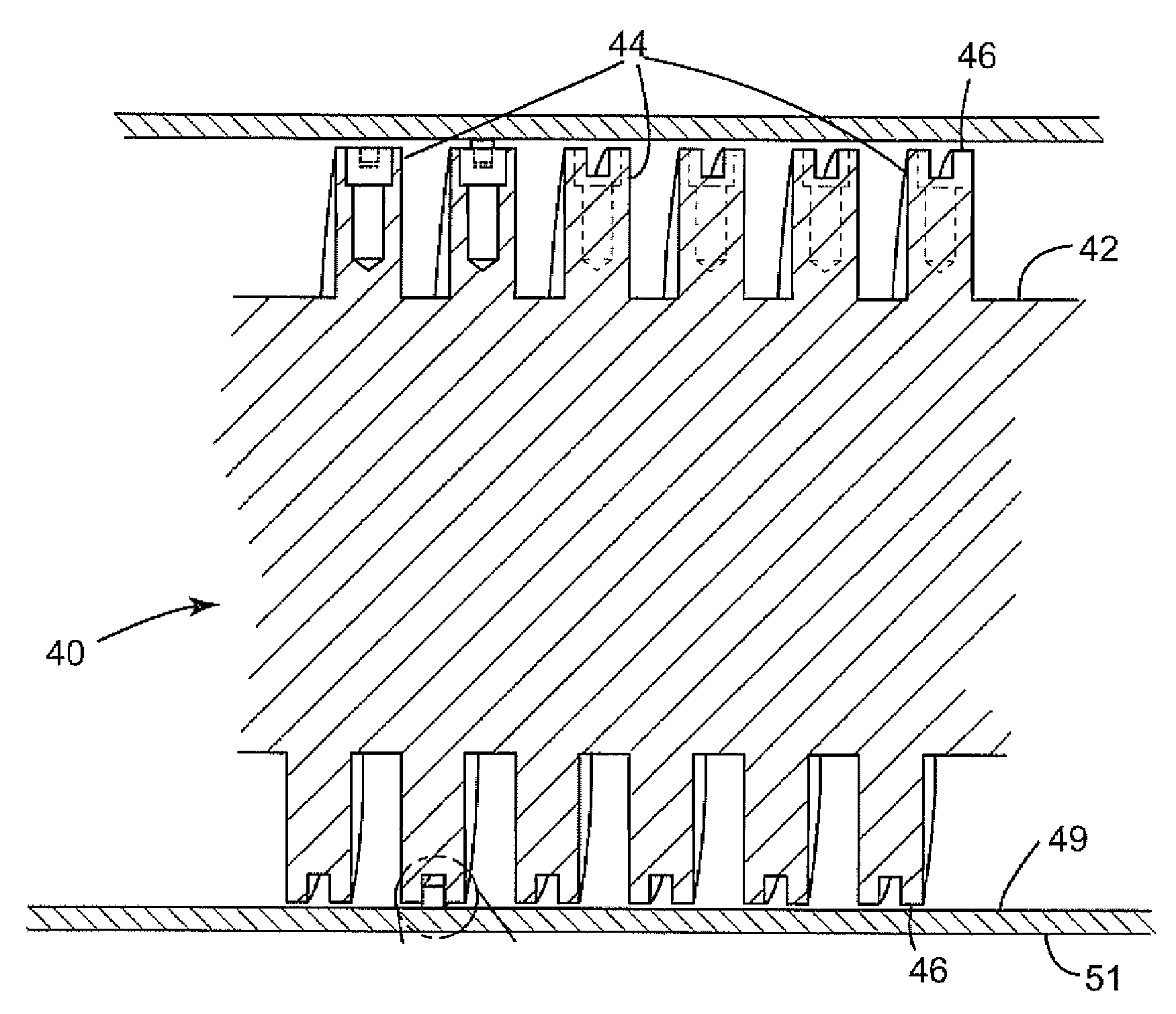
[0025]FIGS. 3-5 illustrate, respectively, a cross section view of a rotor 40, a cross sectional view of one tip of the screw threads of FIG. 3, and a ring seal 60 in accordance with an embodiment of the disclosed invention. Throughout this disclosure, the terms “ring seal,”“piston-ring seal,”“brush seal,”“inter-stage seal,”“split-ring seal,” or “seal” will be used interchangeably. As shown in FIG. 3, the rotor 40 includes a shaft 42, on the periphery of which a plurality of screw threads 44 ...


PUM


Abstract

A pump rotor for a screw pump includes a shaft, a first set of threads disposed on a portion of an outer surface of the shaft, at least one thread of the first set of threads including a groove disposed on an end portion thereof, and a ring seal disposed on the groove such that the ring seal is configured to protrude outwardly from the groove and to rest against an inner surface of a liner of the screw pump, and the groove is sized so as to allow the ring seal to move radially with respect to the plurality of threads as the rotor is deflected.

Description

BACKGROUND OF THE INVENTION[0001]1. Field of the Invention[0002]The present invention relates in general to screw pumps, and, more particularly, to improved screw pump rotors and methods of reducing slip flow in screw pumps.[0003]2. Description of the Related Art[0004]In the exploration for oil and gas the need to transport fluids (oil, water, gas, and foreign solids) from a wellhead to distant processing and / or storage facilities (instead of building new processing facilities near the wellheads) is well understood. Twin-screw pumps are increasingly being used to aid in the production of these wellhead fluids, resulting in increased production by lowering the pressure at the exit of the wellhead as well as a greater total recovery from the reservoir by allowing lower final reservoir pressures before abandoning production.[0005]FIG. 1 illustrates a conventional twin-screw pump 10. This figure is presented simply to illustrate the main components of a twin-screw pump and should not be...

Claims


Application Information

Patent Timeline
IPC IPC(8): F04D3/02F04D29/18
CPCF04C18/16F04C2210/24F04C27/001F04C29/00F04C27/00
Inventor KOTHNUR, VASANTH SRINIVASAANDERSON, DAVID DELOYD
Owner NUOVO PIGNONE TECH SRL
Why Eureka
Try Eureka