Micromechanical rotation rate sensor having error suppression

a technology of rotation rate sensor and micromechanical technology, which is applied in the direction of acceleration measurement using interia force, turn-sensitive devices, instruments, etc., can solve the problems of suppressed electronically, main axis systems of mass tensors and spring stiffness tensors no longer agreeing with kd, and increasing dynamic range demands, so as to reduce the capture range of regulation, reduce the output noise of the sensor, and reduce the resolution of the regulation

Active Publication Date: 2009-04-28
ROBERT BOSCH GMBH
View PDF6 Cites 10 Cited by
  • Summary
  • Abstract
  • Description
  • Claims
  • Application Information

AI Technical Summary

Benefits of technology

[0017]The rotary sensor may have a control which generates an additional compensation signal from adjustment information. Such a combination of the regulation with a control unifies aspects of the compensation of a change in the interference signal over the running time or service life of the sensor using a fixed adjustment during manufacturing. Because of the additional adjustment, the capture range of the regulation may be decreased, and the resolution of the regulation may be increased. The resolution may be selected so that the output noise of the sensor is not significantly increased by quantization effects of the control circuit in response to a digital arrangement of the regulation. On the other hand, the combined capture range of regulation and control is able to be implemented very large.
[0018]The regulating device may be provided such that a capture range of the regulation may be able to be adjusted as a function of the adjustment value. This may make possible a capture range adjustment of the control circuit to the operating point. Consequently, the F of the Control circuit is independent of the operating point set via the adjustment.
[0019]Furthermore, there may come about a reduction in the requirements on the size of the maximum interference signal of the mechanical sensor element, because this interference signal, using the regulation hereof, may be simply compensated by a suitably selected F. This may decrease the accuracy requirements and consequently the manufacturing costs for the mechanical sensor element.

Problems solved by technology

Typical causes for these generally slight rotations are, for example, asymmetries in the sensor structure caused by imperfections in the manufacturing process.
As a result, the main axis systems of the mass tensors and the spring stiffness tensors no longer agree with KD.
Furthermore, the quadrature signal also has to pass the primary signal conversion paths at the detection device, it can only be suppressed electronically relatively late in the signal path.
In the case of quadrature signals that are large compared to the rotation rate range, this means drastically increased demands on the dynamic range of the first signal conversion steps, and often leads to increased sensor noise.
Furthermore, there may come about a reduction in the requirements on the size of the maximum interference signal of the mechanical sensor element, because this interference signal, using the regulation hereof, may be simply compensated by a suitably selected F. This may decrease the accuracy requirements and consequently the manufacturing costs for the mechanical sensor element.

Method used


Image

  • Micromechanical rotation rate sensor having error suppression
  • Micromechanical rotation rate sensor having error suppression
  • Micromechanical rotation rate sensor having error suppression

Examples


Embodiment Construction

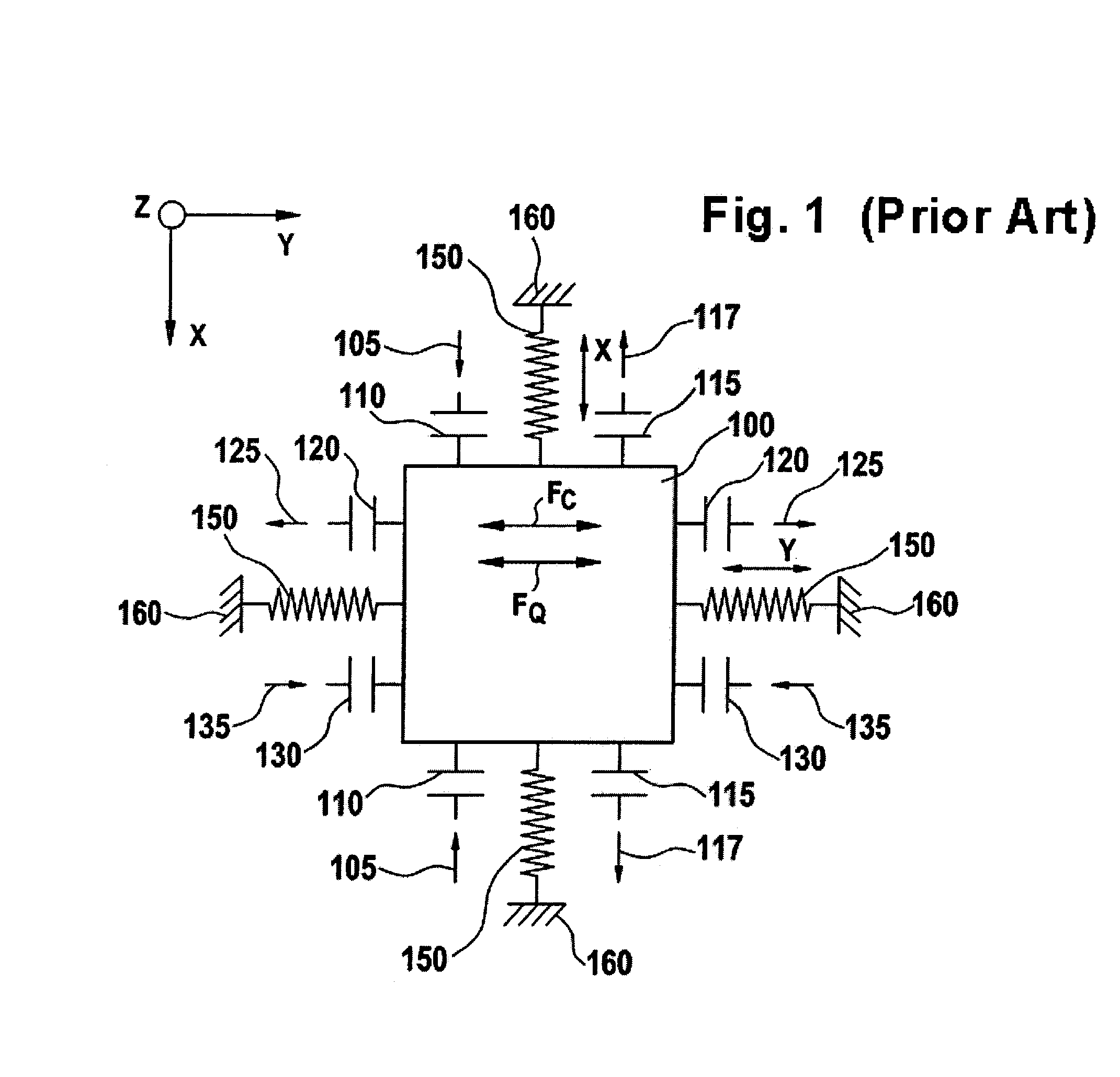
[0034]FIG. 1 schematically illustrates a micromechanical functional part of a conventional rotation rate sensor. What is illustrated is a seismic mass 100 which is suspended using spring elements 150 on a substrate 160. Spring elements 150 are arranged on seismic mass 100 such that seismic mass 100 is able to execute a driving vibration in a first direction x and a deflection in a second direction y that is perpendicular to it. For the driving of seismic mass 100 in the first direction x, driving devices 110 are provided. These driving devices 110 may be arranged capacitively, for example. Therefore, they are illustrated schematically as capacitors. A drive signal 105 is supplied to driving device 110. On seismic mass 100, additional drive measuring devices 115 are provided, which measure the deflection of seismic mass 100 in first direction x, and generate from it a drive vibration signal 117. Drive measuring devices 115, in this example, are also arranged to be capacitive, and are...


PUM


Abstract

A micromechanical rotation rate sensor has a seismic mass and driving devices which cause a driving vibration of the seismic mass in a first direction x. The rotation rate sensor has measuring devices which measure a deflection of the seismic mass in a second direction y, and generate a deflection signal. The deflection includes a measurement deflection caused by a Coriolis force and an interference deflection, the interference deflection being phase-shifted with respect to the measurement deflection by 90°. Compensation devices are provided at the seismic mass to reduce the interference deflection. Regulation devices are provided, to which the deflection signal is supplied as an input variable, which demodulate an interference deflection signal from the deflection signal, and which generate a compensation signal from the interference deflection signal, which is supplied to the compensation devices.

Description

CROSS-REFERENCE TO RELATED APPLICATIONS[0001]The present application claims priority to application Ser. No. 10 2004 061 804.6, filed in the Federal Republic of Germany on Dec. 22, 2004, which is expressly incorporated herein in its entirety by reference thereto.FIELD OF THE INVENTION[0002]The present invention relates to a micromechanical rotation or yaw rate sensor having a seismic mass and having a driving device which causes a driving vibration of the seismic mass in a first direction x. The rotation rate sensor has a measuring device which measures a deflection of the seismic mass in a second direction y, and generates a deflection signal. In this context, the deflection includes a measurement deflection, as a result of a Coriolis force and an interference deflection, the interference deflection being phase-shifted with respect to the measurement deflection, essentially by 90°. A compensation device is provided at the seismic mass in order to prevent the interference deflection...

Claims


Application Information

Patent Timeline
Patent Type & Authority Patents(United States)
IPC IPC(8): G01P15/08G01C19/56
CPCG01C19/5726G01C19/5755
Inventor WILLIG, RAINERKUHLMANN, BUCKHARDGOMEZ, UDO-MARTINBAUER, WOLFRAMCLASSEN, JOHANNESLANG, CHRISTOPHVEITH, MICHAEL
Owner ROBERT BOSCH GMBH
Why Eureka
Try Eureka