Blow-by gas processing apparatus

a processing apparatus and blow-by gas technology, which is applied in the direction of crankcase ventilation, combustion engines, machines/engines, etc., can solve the problems of losing the negative pressure of the intake air, and it is practically impossible to introduce the intake air into the interior of the engine at the supercharging time, so as to achieve efficient ventilation of the interior of the engine

Inactive Publication Date: 2009-04-28
TOYOTA JIDOSHA KK
View PDF25 Cites 25 Cited by
  • Summary
  • Abstract
  • Description
  • Claims
  • Application Information

AI Technical Summary

Benefits of technology

[0017]An objective of the present invention is to provide a blow-by gas processing apparatus which can efficiently ventilate the interior of an engine.

Problems solved by technology

In the case that the supercharger is provided in the internal combustion engine, if the supercharger is operated, the intake negative pressure is lost.
However, in the blow-by gas processing apparatuses in the publications mentioned above, it is practically impossible to introduce the intake air into the interior of the engine at the supercharging time.

Method used


Image

  • Blow-by gas processing apparatus
  • Blow-by gas processing apparatus
  • Blow-by gas processing apparatus

Examples


first embodiment

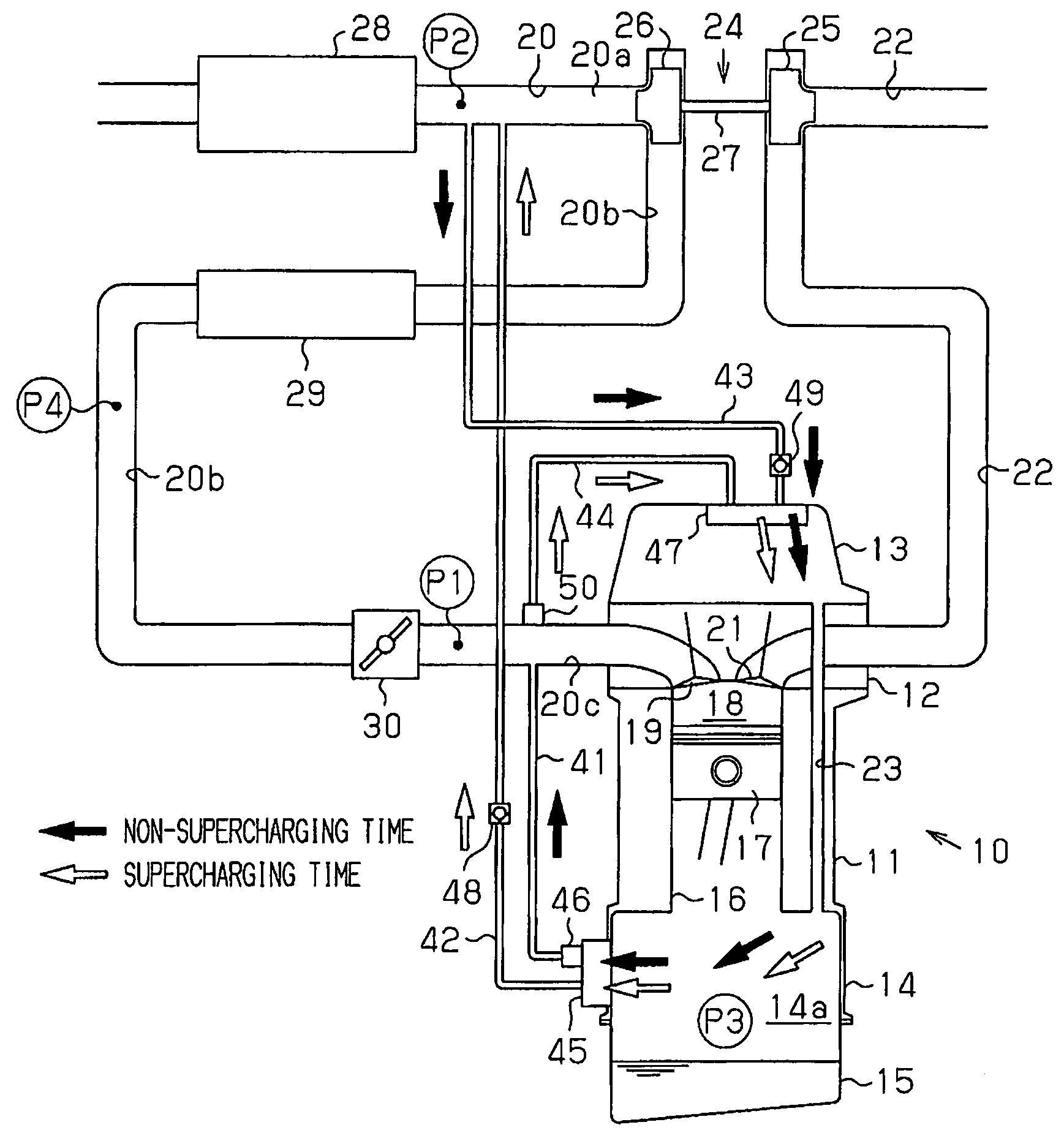
[0070]The first embodiment has the following advantages.

[0071](1) At the non-supercharging time, the intake air within the first introduction passage 43 is introduced to the interior of the head cover 13. The blow-by gas in the crank chamber 14a flows through the first breather passage 41 so as to be discharged to the intake passage 20. At the supercharging time, the intake air within the downstream portion 20c flows through the second introduction passage 44 so as to be introduced to the interior of the head cover 13. The blow-by gas in the crank chamber 14a flows through the second breather passage 42 so as to be discharged to the upstream portion 20a. Accordingly, the flow in the engine 10 is not changed between the supercharging time and the non-supercharging time, and it is possible to efficiently ventilate the blow-by gas in the engine 10.

[0072](2) The second introduction passage 44 is provided with the second PCV valve 50. Accordingly, it is possible to regulate the intake ai...

third embodiment

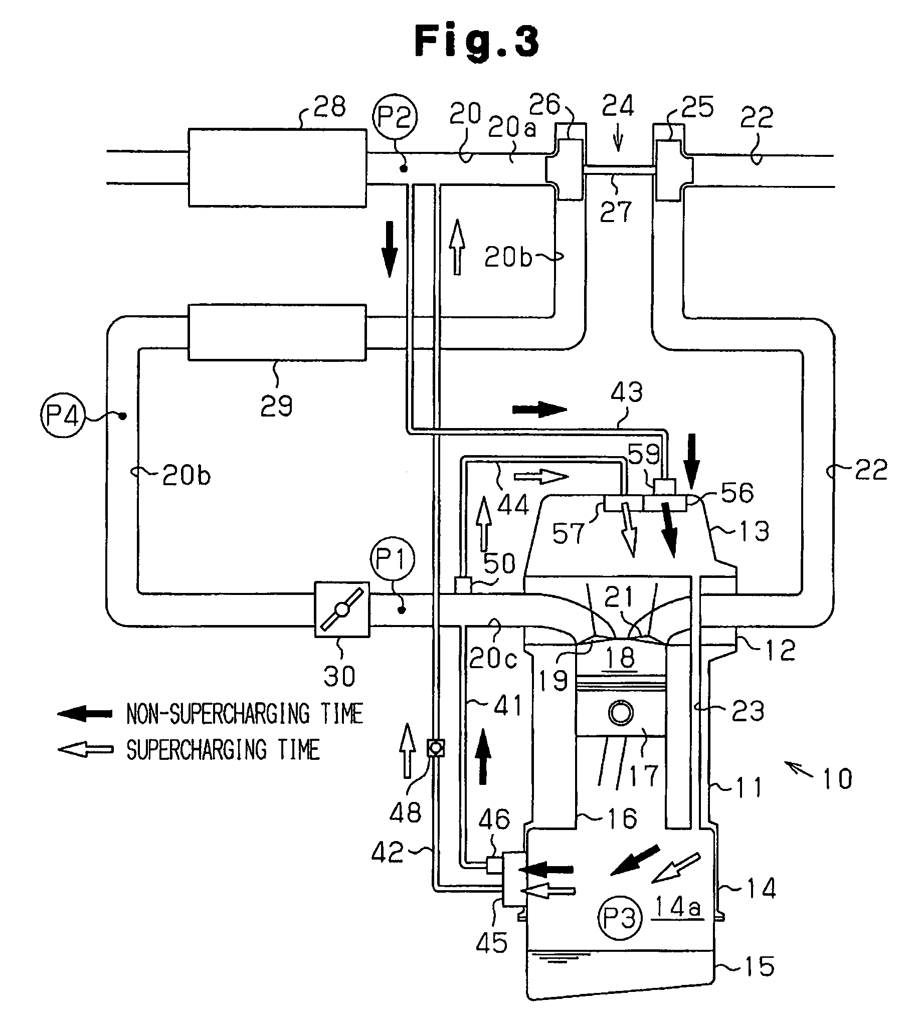
[0080]FIG. 3 shows a blow-by gas processing apparatus in accordance with the present invention. The check valve 49 shown in FIG. 1 is deleted from the first introduction passage 43, and the first introduction passage 43 is provided with a throttle portion 59. The throttle portion 59 reduces a passage cross-sectional area of the first introduction passage 43. At the non-supercharging time, the first introduction passage 43 introduces the intake air to the interior of the head cover 13 from the intake passage 20 on the basis of the pressure difference between the downstream pressure P1 and the upstream pressure P2. At the supercharging time, the second introduction passage 44 introduces the intake air to the interior of the head cover 13 from the intake passage 20 on the basis of the pressure difference between the upstream pressure P2 and the downstream pressure P1.

[0081]As shown in FIG. 3, the second introduction passage 44 is provided with the second PCV valve 50 serving as the one...


PUM


Abstract

An intake passage has an upstream portion in an upstream side of a supercharger, an intermediate portion between a supercharger and a throttle valve, and a downstream portion in a downstream side of the throttle valve. A first breather passage connects an interior of an engine with the downstream portion. A second breather passage connects the interior of the engine with the upstream portion. Introduction passages communicate the upstream portion with the interior of the engine at a non-supercharging time, and connect at least one of the intermediate portion and the downstream portion with the interior of the engine at a supercharging time. Thus, the interior of the engine is efficiently ventilated.

Description

BACKGROUND OF THE INVENTION[0001]The present invention relates to a blow-by gas processing apparatus which is applicable to an internal combustion engine provided with a supercharger.[0002]A vehicle internal combustion engine can be provided with, for example, a blow-by gas processing apparatus. The blow-by gas processing apparatus recirculates a combustion gas leaking to a crank chamber from a gap between a cylinder and a piston of the engine, that is, a blow-by gas to an intake passage. Specifically, an intake negative pressure generated in a portion of the intake passage in a downstream side of a throttle valve draws the blow-by gas in an interior of the engine so as to circulate in a breather passage. The blow-by gas is returned to the intake passage from the breather passage, is again fed to the combustion chamber, and is burned. Accordingly, it is possible to reduce a discharge amount of a hydrocarbon (HC) to the atmosphere. Further, it is possible to inhibit the blow-by gas f...

Claims


Application Information

Patent Timeline
Patent Type & Authority Patents(United States)
IPC IPC(8): F01M13/00F01M13/02
CPCF01M13/02F01M13/021F01M13/028F01M2013/027
Inventor HIRANO, SATOSHIOKADA, NAOYAIKEDA, JUN
Owner TOYOTA JIDOSHA KK
Why Eureka
Try Eureka