Mixer for use with media in wastewater treatment

a technology of wastewater treatment and media, which is applied in the direction of multi-stage water/sewage treatment, filtration separation, separation processes, etc., can solve the problems of slowing down the progress of wastewater treatment, the amount of tiny bubbles that must be supplied to provide adequate mixing will greatly exceed the quantity of tiny bubbles required for sufficient oxygenation, and the effect of enhancing the efficiency of wastewater conversion

Active Publication Date: 2009-04-28
KOOPMANS RICHARD J +1
View PDF21 Cites 14 Cited by
  • Summary
  • Abstract
  • Description
  • Claims
  • Application Information

AI Technical Summary

Benefits of technology

[0014]Embodiments of the present invention comprise a tank for treating wastewater and include an aerobic zone in which bacteria and other microorganisms consume pollutants in the presence of dissolved oxygen, and an anoxic zone in which bacteria and other microorganisms convert pollutants in the absence of dissolved oxygen to a more environmentally friendly form. Advantageously, the tank also includes a mixer that generates large mixing bubbles, for example a bubble having a largest dimension of 6 inches to 10 feet. In some embodiments, the mixer is located in the anoxic zone. The mixing bubbles are large enough to move wastewater as they rise to the surface and generate a mixing current in the wastewater. The mixing current mixes the wastewater, and bacteria and other microorganisms to promote the bacteria and other microorganisms' conversion of the pollutants contained in the wastewater. The present invention advantageously further comprises an Integrated Fixed-film Activating Sludge (IFAS) system, enhancing the efficiency of wastewater conversion.

Problems solved by technology

The prior art means for mixing the wastewater in the aerobic and anoxic zones is subject to limitations and disadvantages.
As the demand for dissolved oxygen diminishes with aerobic treatment over time, the amount of tiny bubbles that must be supplied to provide adequate mixing will greatly exceed the quantity of tiny bubbles required for sufficient oxygenation.
Using the tiny bubbles for mixing when wastewater oxygen demand has diminished, the diffusers consume more power than required to oxygenate the wastewater and can inject more dissolved oxygen into the aerobic zone than required, in fact thereby potentially slowing the progress of the wastewater treatment.
Mixing the aerobic and anoxic zones with a mechanical mixer consumes a large amount of power relative to the amount of wastewater that it mixes, and often mixes some, but not all, of the wastewater in each zone.
It may appear even to those skilled in the art that the presence of IFAS in such a wastewater treatment system would present a physical barrier, whereby large mixing bubbles are broken up with the consequent loss of the advantages afforded by employing such bubbles for mixing.

Method used


Image

  • Mixer for use with media in wastewater treatment
  • Mixer for use with media in wastewater treatment
  • Mixer for use with media in wastewater treatment

Examples


Embodiment Construction

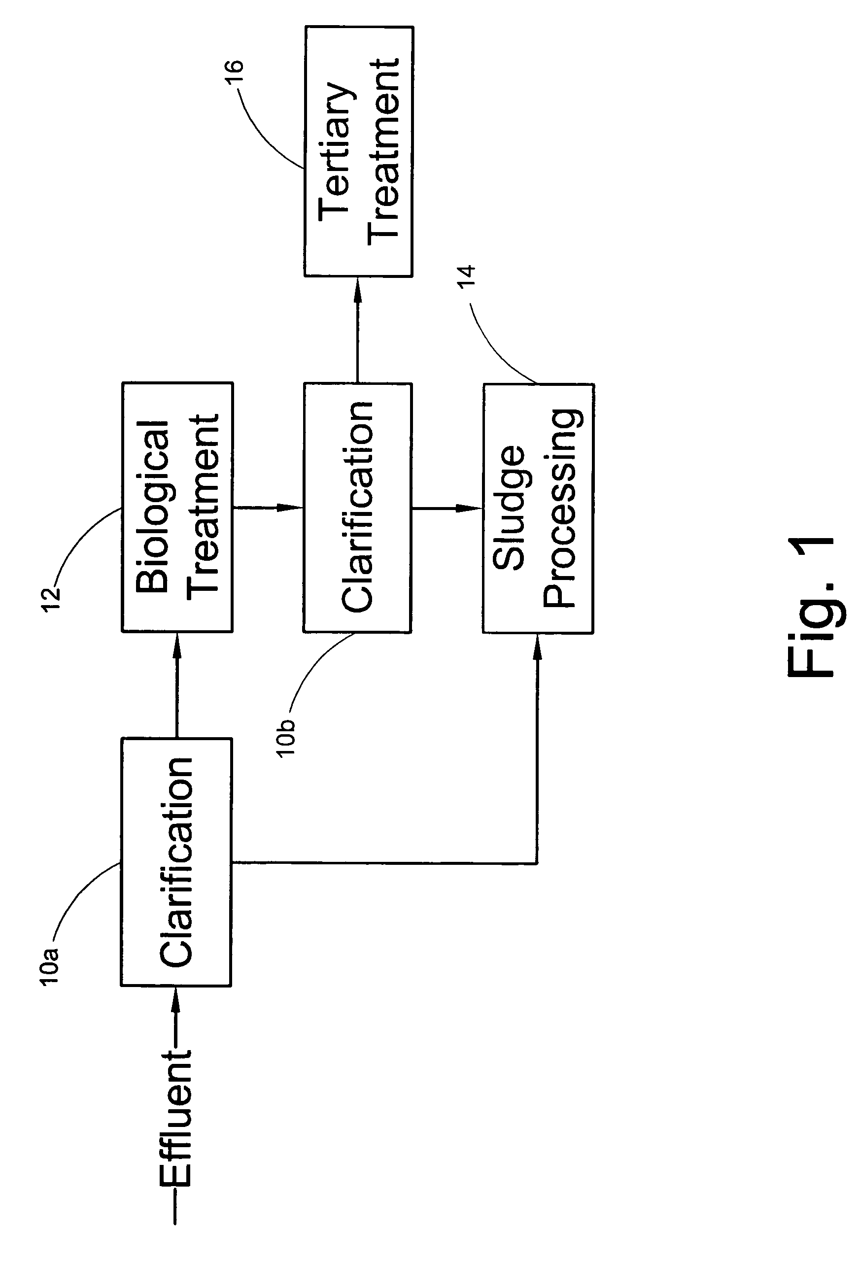
[0023]FIG. 1 is a schematic diagram of a wastewater treatment process that includes a primary treatment process, a secondary treatment process and a tertiary treatment process. The primary treatment process includes a clarification stage 10a to separate dense portions of the wastewater, typically heavy solids, from less dense portions of the wastewater, typically light solids and liquid. The secondary treatment process includes a biological nutrient conversion stage 12 that converts the biological nutrient material contained in the light solids and liquid into a more environmentally friendly form. For example, in one embodiment, wastewater is first clarified into heavy solids, light solids and supernatant liquid in the clarification stage 10a using conventional techniques. The heavy solids are directed to a sludge processing stage 14 that processes the heavy solids using conventional techniques. The light solids and liquid are directed to the biological nutrient conversion stage 12 ...


PUM

PropertyMeasurementUnit
diameteraaaaaaaaaa
diameteraaaaaaaaaa
sizeaaaaaaaaaa

Abstract

A system for wastewater treatment comprises a tank and includes a mixer that generates large mixing bubbles, for example a bubble having a largest dimension of 6 inches to 10 feet. In some embodiments, the mixer is located in the anoxic zone. The mixing bubbles are large enough to move wastewater as they rise to the surface and generate a mixing current in the wastewater. The mixing current mixes the wastewater, and bacteria and other microorganisms to promote the bacteria and other microorganisms' conversion of the pollutants contained in the wastewater. The system further comprises an Integrated Fixed-film Activating Sludge (IFAS) system.

Description

CROSS REFERENCE TO RELATED APPLICATION[0001]This application claims priority from U.S. provisional application No. 60 / 681,718, filed May 16, 2005, entitled MIXER FOR USE IN WASTEWATER TREATMENT PROCESSES.BACKGROUND[0002]Water is frequently used to transport unwanted materials—waste—to a facility where the waste is removed or neutralized in the water. For example, water carries most sewage and industrial waste, such as chemicals, in the form of wastewater to a treatment facility where the water is treated and then returned to the environment for future use. The wastewater treatment process typically includes three general phases. The first phase, or primary treatment, involves mechanically separating the dense solids in the wastewater from the less dense solids and liquid in the wastewater. This is typically done in sedimentation tanks with the help of gravity. The second phase, or secondary treatment, involves the biological conversion of carbonaceous and nutrient material in the wa...

Claims


Application Information

Patent Timeline
Patent Type & Authority Patents(United States)
IPC IPC(8): C02F3/30C02F3/06
CPCC02F3/06C02F3/1284C02F3/20C02F3/30Y02W10/10
Inventor KOOPMANS, RICHARD J.DREWRY, KRISTINN G.
Owner KOOPMANS RICHARD J
Why Eureka
Try Eureka