
Battery comprising a flange formed at a peripheral edge and a protection circuit attached to the flange

Inactive Publication Date: 2009-04-28
HITACHI MAXELL ENERGY LTD
View PDF29 Cites 6 Cited by
  • Summary
  • Abstract
  • Description
  • Claims
  • Application Information

AI Technical Summary

Benefits of technology

[0020]Embodiments of the present invention provide a battery with a novel configuration that can solve the above-mentioned possible problems in terms of a shape, attachment, strength, productivity, and the like in thinning of a battery.

Problems solved by technology

When the battery is fixed with an adhesive, an increase in thickness of the equipment can be avoided; however, it is difficult to separate the battery for disposal, which is likely to have detrimental effects in modern time as recycling is important.
Furthermore, the conventional thin battery configuration as described in the above (1) to (3) cannot sufficiently meet the demand for further thinness.
Alternatively, even if a battery can be made thinner, its strength may not be sufficient, inconvenience is likely to occur in the course of production, it is not easy to set the battery on equipment, etc.
Thus, various problems occur.
For example, the thinnest can has a thickness of about 3 mm, and it is impossible or very difficult to obtain a can with a thickness of about 3 mm or less by the current deep-drawing technique.
Therefore, in order to obtain such a thin battery can, a stacked material such as a laminate as described above cannot help being used as a battery outer member.
In this case, although the thinness of the laminate can be ensured, the strength of the laminate with respect to sticking and bending is smaller than that of a metal can, and furthermore, there is a possibility of swelling of a battery and leakage of liquid.
Furthermore, even if a metal can with a thickness of 3 mm or less can be formed, a deep-drawn can has the following problems.
(A) As the thickness of a metal can is decreased, the width of an opening thereof (opening width in a thickness direction of the can) is decreased, whereby it becomes difficult to insert an electrode in the metal can.
Therefore, when the metal cover is fitted to the opening and bonded thereto by laser welding or the like, the insulating packing is likely to be melted due to welding heat between the metal cover and the can.
Therefore, the kind of metal to be formed is limited, and the hardness of metal to be formed is small.
Therefore, a deep-drawn can is weak to the swelling of a battery.
Thus, materials that have a large hardness (i.e., that are hard), light weight and strength cannot be used even if desired.
(a) For example, a peripheral edge of the maximum opening of a can is provided with a cover having the same size as that of the peripheral edge, and the vicinity of the peripheral edge of the maximum opening is welded. Therefore, welding heat is likely to be transmitted to an electrode body (electrode element) in a can and components placed near the welded portion, which may have thermal influence.
(b) In the case where a cover is attached by crimping an outer periphery of the cover and the peripheral edge of an opening (i.e., by seaming), instead of welding, productivity is decreased compared with the case using welding, and there may be a possibility of leakage of liquid from the connected portion between the outer periphery of the cover and the peripheral edge of the opening.
(c) A battery has a simple prismatic shape although it is thin. Therefore, in order to provide a protection circuit required in a secondary battery, it is necessary to separately keep or provide a space for the protection circuit or a base for attachment thereof.
(d) It is necessary to provide a battery chamber for attaching a battery to equipment or a resin pack (battery pack) or to fix a battery at a predetermined position with a double-faced tape or an adhesive. Thus, there are problems similar to those in the case of a prismatic or cylindrical thin battery as described above.

Method used


Image

  • Battery comprising a flange formed at a peripheral edge and a protection circuit attached to the flange
  • Battery comprising a flange formed at a peripheral edge and a protection circuit attached to the flange
  • Battery comprising a flange formed at a peripheral edge and a protection circuit attached to the flange

Examples


Embodiment Construction

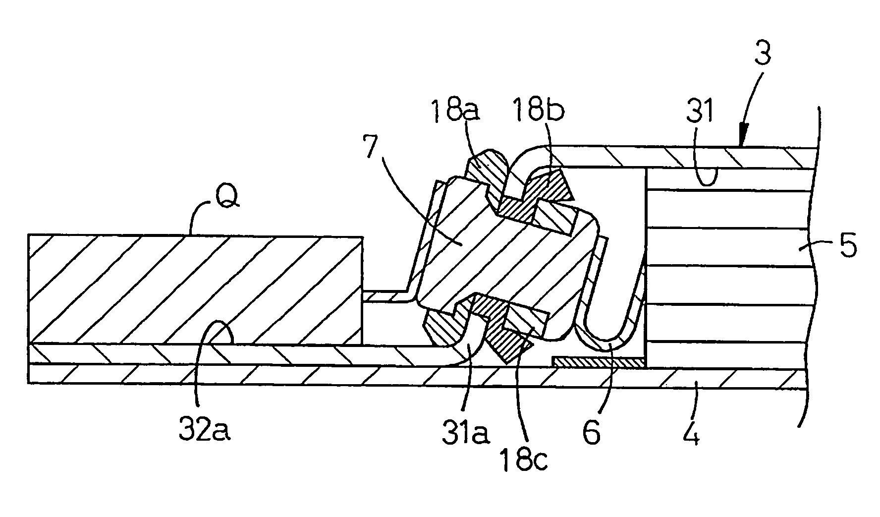
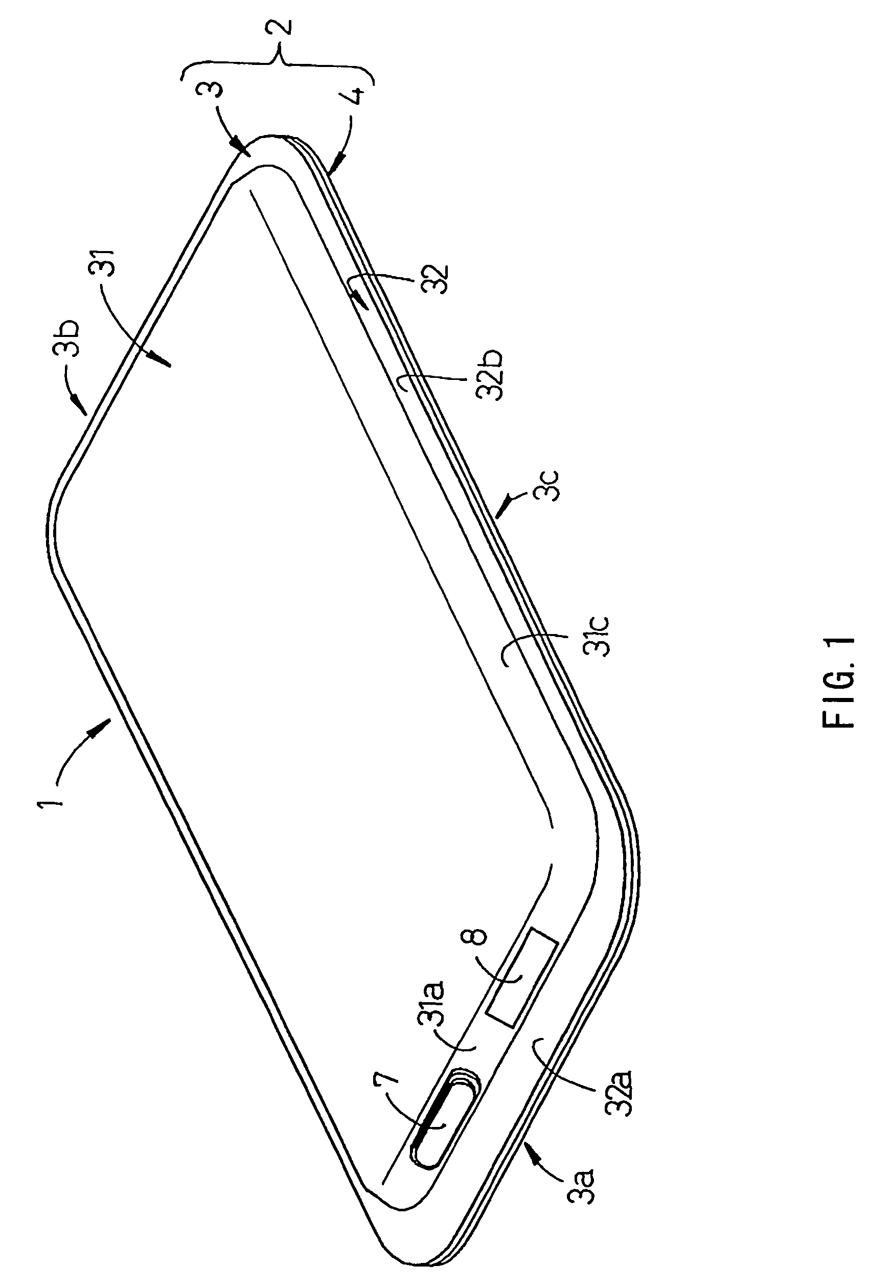
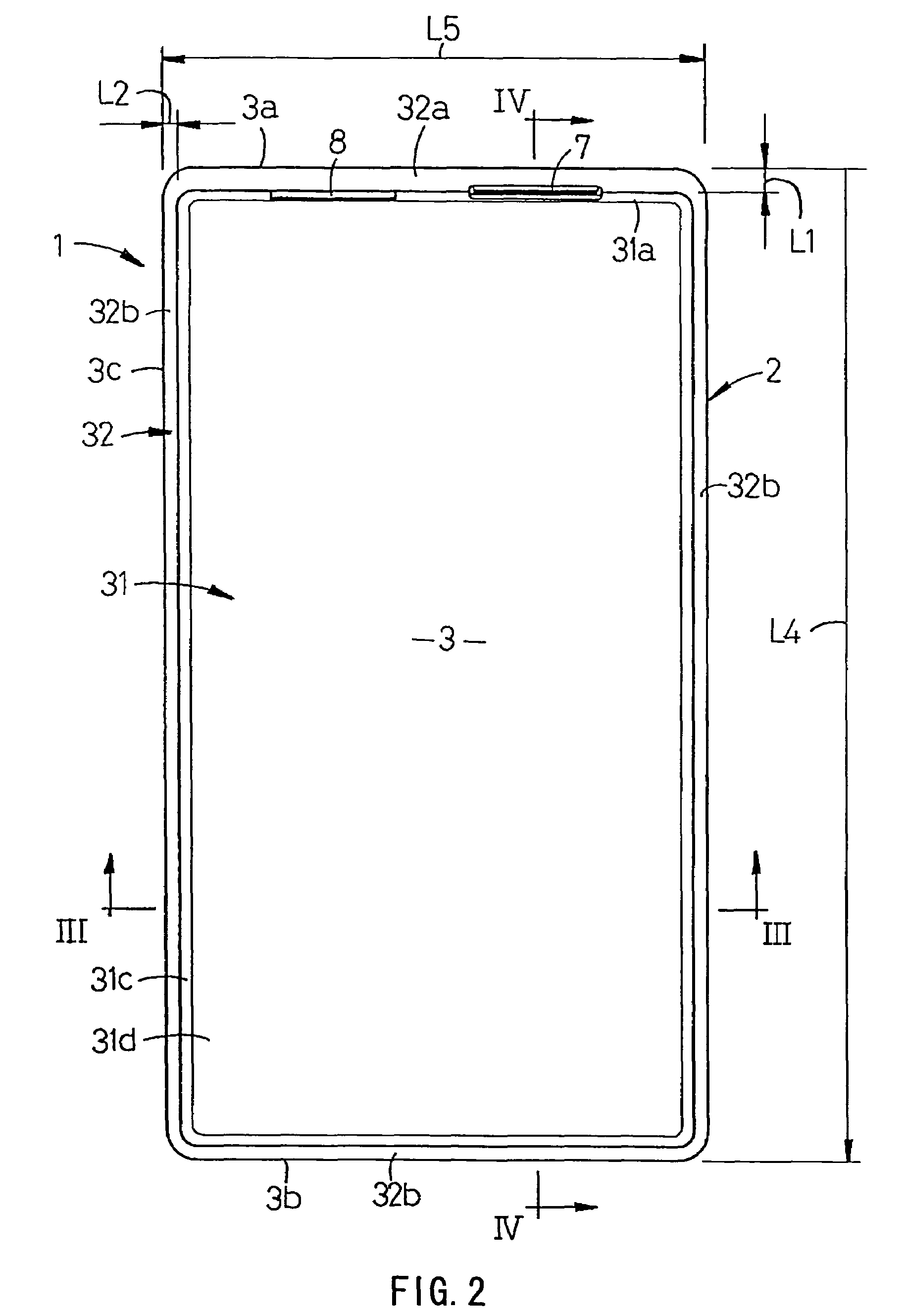
[0055]FIGS. 1 to 6 show an example in which one embodiment of the present invention is applied to a prismatic lithium ion secondary battery (hereinafter, referred to as a “battery”). As shown in FIGS. 1 and 2, a battery 1 has a battery can 2 that has a prismatic shape in a plan view (state in FIG. 2) provided with four rounded corners. As shown in FIGS. 1 to 4, the battery can 2 is composed of a can body 3 having a concave portion 31, and a metal cover 4 for sealing an opening end of the concave portion 31 of the can body 3.

[0056]The can body 3 is formed in a plate shape by subjecting one metal plate (sheet plate) to shallow drawing, and a flat flange 32 is formed along an entire periphery of a peripheral edge of the opening end. In the flange 32, a width (flange width) L1 of a flange portion (first flange portion) 32a at a first short side portion 3a positioned on a upper end side of the can body 3 in the state shown in FIG. 2 is larger by 1 mm or more than a width (flange width) L...


PUM


Abstract

A battery can 2 is composed of a can body 3 having a concave portion 31 for accommodating an electrode body 5, and a metal cover 4 for sealing an opening end of the concave portion 31 of the can body 3. The can body 3 is formed in a plate shape by subjecting a metal plate to shallow drawing. A flange 32 is provided at a peripheral edge portion of the opening end of the can body 3, which is bonded to be integrated with the metal cover 4 to keep an air-tight and liquid-tight state in the concave portion 31.

Description

TECHNICAL FIELD[0001]The present invention relates to a battery suitable for use as a power source of small electronic equipment such as portable electronic equipment, and in particular, to a configuration of a thin battery.BACKGROUND ART[0002]Batteries used as power sources of electronic equipment have, for example, a cylindrical shape or a prismatic shape. In a cylindrical battery, a metal can deep-drawn to a cylindrical shape (cylindrical drawing) is used, and in a prismatic battery, a metal can deep-drawn to a prismatic shape (prismatic drawing) is used.[0003]On the other hand, in small portable electronic equipment such as a portable information terminal requiring thinness, a relatively thin battery is used. This kind of thin battery is classified into the following types.[0004](1) A thin battery in which a metal can (deep-drawn can) subjected to the above-mentioned deep-drawing is used, and a metal cover is fitted to an opening of the metal can, followed by welding (e.g., see ...

Claims


Application Information

Patent Timeline
IPC IPC(8): H01M2/08H01M2/04H01M2/02H01M2/10H01M2/12H01M2/30H01M10/04H01M10/34H01M10/42
CPCH01M2/0426H01M2/1061H01M10/0436H01M10/425H01M2/0217H01M10/34Y02E60/10H01M50/103H01M50/169Y02P70/50
Inventor SOMATOMO, YOSHIKIWATANABE, OSAMUTANAKA, MASATOSHI
Owner HITACHI MAXELL ENERGY LTD
Features
  • Generate Ideas
  • Intellectual Property
  • Life Sciences
  • Materials
  • Tech Scout
  • Unparalleled Data Quality
  • Higher Quality Content
  • 60% Fewer Hallucinations
Learn More