Liquid or gas sensor and method

a technology of liquid or gas sensor and sensor body, which is applied in the direction of sensors, printed circuit aspects, and fluid analysis using sonic/ultrasonic/infrasonic waves. it can solve the problems of deteriorating quality, adversely affecting analysis, and the process of producing gas cells is a relatively complex and expensive task. it is simple and inexpensive to construct, accurate and compact

Inactive Publication Date: 2009-04-28
MEDAIR
View PDF7 Cites 15 Cited by
  • Summary
  • Abstract
  • Description
  • Claims
  • Application Information

AI Technical Summary

Benefits of technology

[0005]The object of the present invention is to provide an accurate and compact fluid sensor that is simple and inexpensive to construct.
[0010]The circuit board may contain via-holes extending through the whole or part of the circuit board to conduct current from one part, or side, of the circuit board to another. These via holes are holes going through the whole, or part, of the circuit board substrate and are also usually gold plated and so are ideal for use as a fluid cell. This means that it is relatively simple to construct a fluid cell in the substrate of a circuit board and that the time required to manufacture a fluid sensor can therefore be significantly reduced as no special tools to manufacture the fluid cell are required and the cost of producing a fluid sensor is consequently significantly reduced. The inventive fluid sensor is more portable than a conventional fluid sensor as it is more lightweight and compact than conventional fluid sensors which have a separate fluid cell, usually made of metal. The inventive fluid sensor may therefore be carried more easily.
[0011]Furthermore the condensation problem is decreased or eliminated since the electric / electronic components mounted on the circuit board generate heat which is conducted through the substrate of the circuit board. As the walls of the fluid cell are consequently heated this prevents condensation from collecting on the inner walls of the of the fluid cell. According to a preferred embodiment of the invention the circuit board of the fluid sensor comprises a heat-generating component in the vicinity of the fluid cell.
[0013]According to another preferred embodiment of the invention the electromagnetic energy source and / or said at least one detector is / are mounted on the circuit board so that the circuit board provides the foundation for the whole fluid sensor however the electromagnetic energy source and said at least one detector may be provided as separate components in communication with the fluid cell that is incorporated into the circuit board. However mounting both of these components on the circuit board is advantageous in that interconnecting wires or cables connecting the components to the circuit board are not needed and this eliminates the noise introduced by such interconnects, decreases the production time and makes the fluid sensor more compact.
[0016]According to another preferred embodiment of the invention the fluid sensor comprises a plurality of fluid cells incorporated into the substrate of the circuit board. Having a plurality of gas cells is advantageous if different sample gases are to be analyzed by the fluid sensor simultaneously. The fluid cells may be arranged so that a fluid may move freely between the fluid cells or from one cell to the next in a specific order. According to another preferred embodiment of the invention the plurality of fluid cells comprises at least one test channel to determine the attenuation at a wavelength not influenced by a fluid that is to be analysed, but close to it, to provide a measure of the variation of the electromagnetic signal influenced by environmental parameters and not by the analysed fluid.

Problems solved by technology

The process of producing a gas cell is therefore a relatively complex and expensive task and requires special tools to produce the gas cell.
Furthermore, when such gas sensors are used condensation collects on the inner walls of the gas cell which deteriorates the quality of the signals passing through the gas cell and this can adversely affect the analysis results.

Method used


Image

  • Liquid or gas sensor and method
  • Liquid or gas sensor and method
  • Liquid or gas sensor and method

Examples


Embodiment Construction

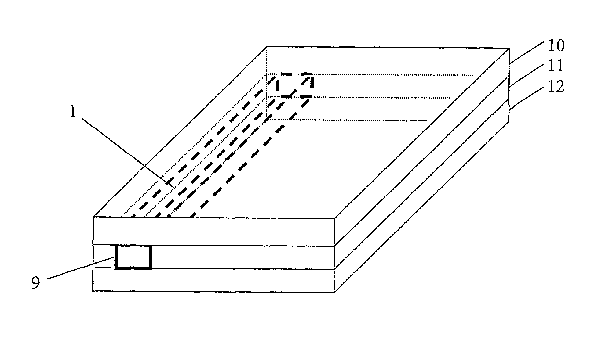
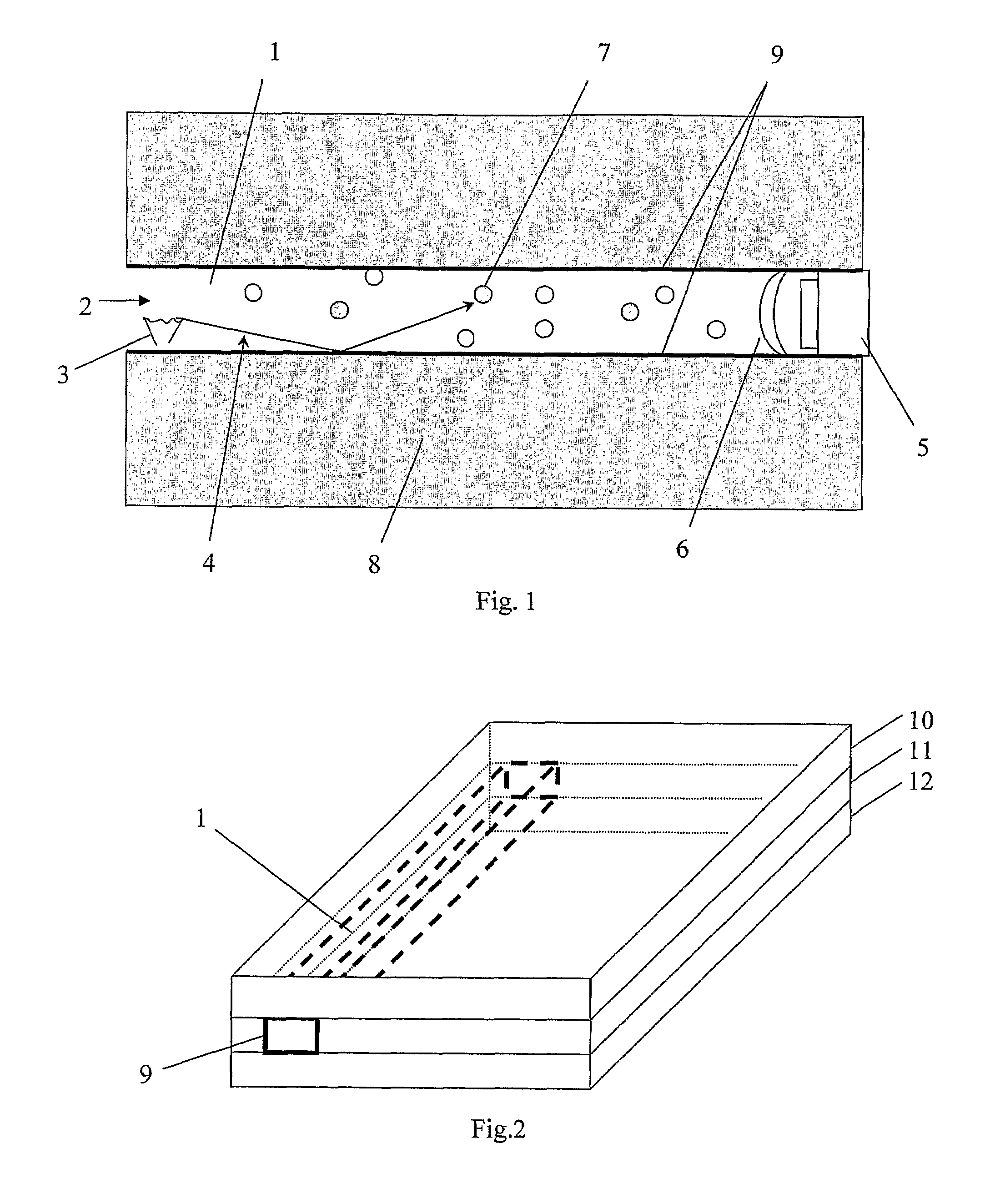
[0027]FIG. 1 shows carbon dioxide sensor containing a gas cell 1 to enclose a volume of gas, such as exhaled air from a person. The gas cell comprises an opening 2 for the inlet / outlet of gas that is to be analysed. The gas sensor comprises an IR-source 3, such as a heated element, arranged to transmit IR-radiation 4 into the gas cell and an IR-detector 5 to detect IR-radiation passing through the gas cell. The gas cell therefore functions as a waveguide for the IR-radiation.

[0028]A filter 6 is placed in front of the detector to eliminate all light except the specific wavelength that carbon dioxide molecules 7 absorb, namely 4.26 μm, which is in the IR-range. The intensity of 4.26 μm light that reaches the detector 5 is inversely proportional to the concentration of carbon dioxide in the sample of gas in the gas cell. When the concentration of carbon dioxide in the chamber is zero, the detector will detect the full light intensity from the IR-source. The exact relationship between I...


PUM

PropertyMeasurementUnit
specific wavelengthaaaaaaaaaa
volumeaaaaaaaaaa
electromagnetic energyaaaaaaaaaa

Abstract

A fluid sensor is provided which contains a fluid cell (1) to enclose a volume of fluid (7), i.e., a gas or liquid, to be analyzed, in addition to a method for producing such a fluid sensor. An electromagnetic energy source (3) is arranged to transmit electromagnetic waves (4) into the fluid cell (1) with at least one detector (5) arranged to detect electromagnetic waves passing through the fluid cell (1) and at least one opening (2) situated for inlet or outlet of the fluid (7) to be analyzed. A circuit board (8, 10, 11, 12, 13, 14, 15, 16) is arranged to evaluate intensity of electromagnetic waves reaching the detector (5) and / or provide circuitry for the electromagnetic energy source (3). At least part of the fluid cell (1) is incorporated into the substrate of the circuit board (8, 10, 11, 12, 13, 14, 15, 16).

Description

BACKGROUND OF THE INVENTIONTECHNICAL FIELD OF THE INVENTION AND PRIOR ART[0001]The present invention concerns a fluid sensor, i.e. a sensor for a gas or a liquid, such as a non-dispersive infrared (NDIR)-type sensor, containing a fluid cell to enclose a volume of gas or liquid that is to be analysed. The fluid sensor comprises an electromagnetic energy source arranged to transmit electromagnetic waves into the fluid cell and at least one detector to detect electromagnetic waves passing through the fluid cell and at least one opening for the inlet / outlet of gas that is to be analysed. The gas sensor also comprises a circuit board to evaluate the intensity of electromagnetic waves reaching said at least one detector and / or to provide the circuitry for the electromagnetic energy source. The present invention also relates to a method for producing such a fluid sensor.[0002]Gas sensors of the NDIR-type are well known in the art. Such sensors comprise a gas cell with an IR-source at one e...

Claims


Application Information

Patent Timeline
Patent Type & Authority Patents(United States)
IPC IPC(8): G01J5/02G01N21/03G01N21/35H05K1/02
CPCG01N21/031G01N21/3504G01N21/61H05K1/0272H05K3/4611H05K2201/10151
Inventor STENBERG, JOHAN
Owner MEDAIR
Why Eureka
Try Eureka