Transformer-based multi-band RF front-end architecture

a transformer and front-end technology, applied in the field of radio communication, can solve the problems of low quality (q) factor, imbalance in the resulting differential signal, and limited integration, and achieve the effect of reducing the area required for each signal path

Inactive Publication Date: 2009-04-28
AVAGO TECH INT SALES PTE LTD
View PDF20 Cites 55 Cited by
  • Summary
  • Abstract
  • Description
  • Claims
  • Application Information

AI Technical Summary

Benefits of technology

[0011]The method and apparatus of the present invention offers improvements over prior art by providing multiple signal paths, with different frequency bands of operation, to be realized with a single transformer thereby reducing the area required for each signal path on an integrated circuit die.

Problems solved by technology

However, such integration has been limited due to flux leakage, capacitive coupling limits, and significant series resistance.
While coplanar interleaved transformers reduce size and resistance and are widely used, they suffer from a low quality (Q) factor, small coupling coefficients and, if used as a balun, the center tap is often at an undesirable location, resulting in an asymmetric geometry.
As is known to those of skill in the art, asymmetry of a transformer winding causes an imbalance in the resulting differential signal and / or an imbalance in the resulting single-ended signal from a differential signal.
While such toroidal and concentric transformers are well suited for multi-layer structures, they suffer from weak coupling, inconvenient center tap locations and are asymmetrical.
Such transformers have high coupling coefficients and relatively small area; however, the secondary is asymmetrical creating a loading asymmetry.
While each of these various embodiments of on-chip transformers have utility and certain applications they do not currently provide for coupling two or more frequency bands through a single transformer.

Method used


Image

  • Transformer-based multi-band RF front-end architecture
  • Transformer-based multi-band RF front-end architecture
  • Transformer-based multi-band RF front-end architecture

Examples


Embodiment Construction

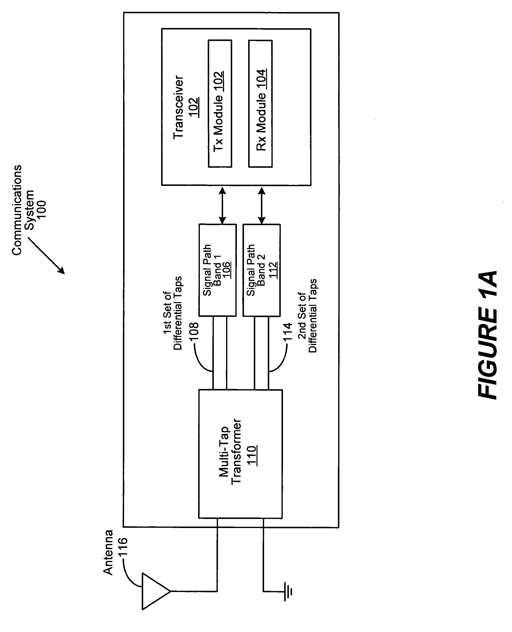
[0030]FIG. 1a is a generalized illustration of a communication system 100 implementing a one embodiment of the invention comprising a multi-tap transformer balun in accordance with the present invention. The communications system comprises a transceiver 102 having a transceiver module 102 operable to generate outbound RF signals and a receiver module 104 operable to receive inbound RF signals. A first signal path 106 is provided by a first set of differential taps 108 coupled to the multi-tap transformer 110, as discussed in greater detail hereinbelow. Likewise a second signal path is provided by a second set of differential taps 114 coupled to the multi-tap transformer 110 (hereinafter sometimes referred to as a “balun”). The two signal paths 106 and 112 are operable to facilitate signals in different frequency bands. In the embodiment of the invention shown in FIG. 1, signals at different frequencies are received and transmitted through a single port to an antenna 116.
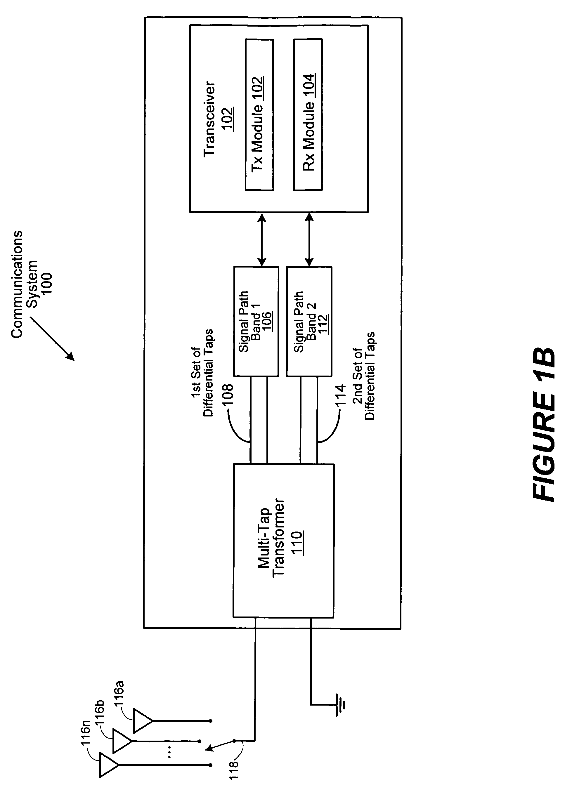
[0031]FIG. 1...


PUM


Abstract

An apparatus and method for allowing two different signal paths to be coupled to a multi-tap transformer balun. The multi-tap transformer has a first port, which is coupled to a single antenna, and two or more differential secondary ports. Each port has one or more taps, which are optimized separately for each of the signal paths, allowing each of the two or more signal paths to operate in different frequency bands. Use of the method of the invention can decrease the number of external components and integrated circuit package pins, and reduce the area required for each signal path on an integrated circuit die, a printed circuit board, or the like.

Description

BACKGROUND OF THE INVENTION[0001]1. Field of the Invention[0002]The present invention relates in general to the field of radio communications and more particularly, to transformers used within communications systems.[0003]2. Description of the Related Art[0004]Two-way radios, which may be incorporated in wireless communication devices, are known to include an antenna, a transformer, a switch, a receiver section, and a transmitter section. The transformer may be a transformer balun (balanced / unbalanced) and is generally used to convert single-ended signals into differential signals and conversely to convert differential signals into single-ended signals. For example, radio frequency (RF) signals received via the antenna are converted into differential signals, which are provided to a low noise amplifier of the receiver section. Conversely, differential signals from a power amplifier of the transmitter section are converted into single-ended signals, which are provided to the antenna....

Claims


Application Information

Patent Timeline
Patent Type & Authority Patents(United States)
IPC IPC(8): H04B1/38H01Q9/28H03H5/00H04B1/44H04B3/00H04L25/00H04L25/06H04L25/10
CPCH04B1/006H04B1/406
Inventor BHATTI, IQBALCASTANEDA, JESUSMARHOLEV, BOJKO F.
Owner AVAGO TECH INT SALES PTE LTD
Why Eureka
Try Eureka