
Business transaction processing systems and methods

a business transaction and processing system technology, applied in the field of business transaction processing systems and methods, can solve the problems of difficult to change the format of hardcoded fso reports that have to be collated by regions, and fso systems which utilize hardcoded software may be more difficult to adapt to the changing processing structur

Active Publication Date: 2009-04-28
COMP SCI A OF NV
View PDF89 Cites 29 Cited by
  • Summary
  • Abstract
  • Description
  • Claims
  • Application Information

AI Technical Summary

Benefits of technology

[0080]In one embodiment, a program executing on an FSO computer system may provide a user interface that may allow a user of the program to construct key definitions for building the processing key values used in locating processing parameters in the FSO system database. The key definitions may be constructed by selecting one or more data elements to be included as key elements in the key definition. The data elements may be displayed for selection in the graphical user interface. The user interface may also provide a method for specifying a sequence in which the key elements will appear in the key definition. The key definitions may be stored in the database in the FSO system. In one embodiment, the key definitions may be stored in a key definition table in the database.
[0105]In one embodiment, a program executing on an FSO computer system may provide a user interface that may allow a user of the program to construct key definitions for building the processing key values used in locating processing parameters in the FSO system database. The key definitions may be constructed by selecting one or more data elements to be included as key elements in the key definition. The data elements may be displayed for selection in the graphical user interface. The user interface may also provide a method for specifying a sequence or map that identifies the arrangement of the key elements in the key definition. The key definitions may be stored in the database in the FSO system. In one embodiment, the key definitions may be stored in a key definition table in the database.

Problems solved by technology

FSO systems which utilize hardcoded software may be more difficult to adapt to the changing processing structure.
FSO systems, which utilize hardcoded software, become more difficult to adapt to the changing processing structure.
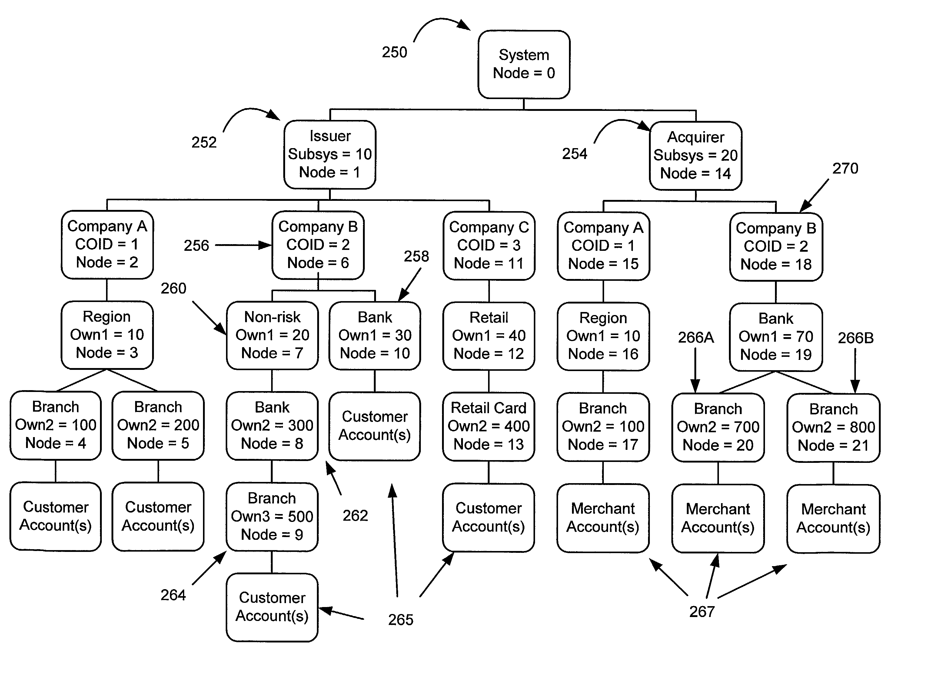
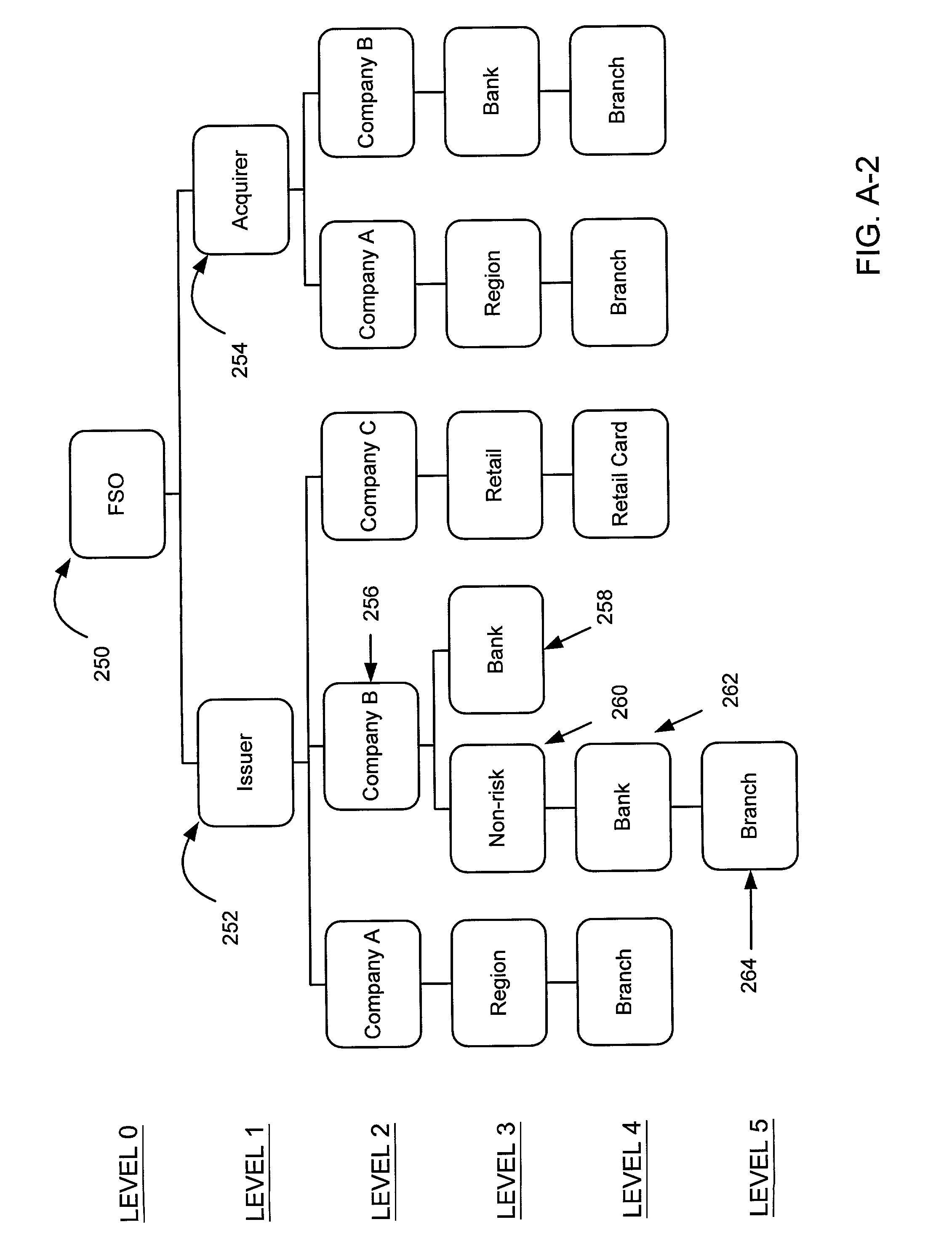
For example, it may be difficult to change the format of a hardcoded FSO report that has to be collated by regions, wherein one of the regions has expanded to cover more branch FSOs.
In many instances, the databases may be extremely large.
However, stored procedures are not event-driven and are not attached to a specific table.
Assuming a master file has millions of records, and each record may have one or more processing tasks associated with it, the process of sequentially accessing every record to determine applicability of a processing task to a specific record is very inefficient and time consuming.
This method has one or more drawbacks, which may limit the usefulness in FSO data set processing applications.
In many instances, the databases may be extremely large.
Database limitations may prohibit the use of multiple environments within the same database sub-system.
The number of multiple databases within one environment within the same database sub-system may also be limited.
These limitations may often substantially reduce the flexibility of the FSO transaction processing application software program to adapt to changing business requirements.
This method is programming intensive, time consuming and costly.
This is especially undesirable in installations, which attempt to operate continuously.
Both of these methods have drawbacks.
The method of adding new data to an existing DB2 database increases the size, often reducing the system performance and increasing maintenance complexity.
The method of changing a database name by using applicable commands in the application programming language i.e. by modifying the source code, significantly increases the development time and the costs.
For example, adding a new company database in an FSO may affect the source code in thousands of application programs.
As a result of the hardcoding of processing parameters and keys, FSO systems are not flexible in the configuration and use of processing parameters.
This inflexibility makes it difficult for the FSO to configure an FSO system to meet custom transaction processing requirements.
As a result of the hardcoding of processing parameters and keys, FSO systems are not flexible in the configuration and use of processing parameters.
Moreover, the time needed to implement and test modifications to existing FSO systems makes it difficult for FSOs to respond to rapidly changing business strategies.

Method used


Image

  • Business transaction processing systems and methods
  • Business transaction processing systems and methods
  • Business transaction processing systems and methods

Examples


Embodiment Construction

[0225]The term “computer system” as used herein generally describes the hardware and software components that in combination allow the execution of computer programs. The computer programs may be implemented in software, hardware, or a combination of software and hardware. A computer system's hardware generally includes a processor, memory media, and Input / Output (I / O) devices. As used herein, the term “processor” generally describes the logic circuitry that responds to and processes the basic instructions that operate a computer system. The term “memory medium” includes an installation medium, e.g., a CD-ROM, or floppy disks; a volatile computer system memory such as DRAM, SRAM, EDO RAM, Rambus RAM, etc.; or a non-volatile memory such as optical storage or a magnetic medium, e.g., a hard drive. The term “memory” is used synonymously with “memory medium” herein. The memory medium may include other types of memory or combinations thereof. In addition, the memory medium may be located...


PUM


Abstract

A system, method and carrier medium for configuring processing relationships among entities of a Financial Service Organization (FSO). A system, method and carrier medium for configuring Financial Service Organization (FSO) application software. A method and system for the selective identification and execution of a specific processing task for one or more records contained in the one or more Financial Service Organization (FSO) data sets. A system and method for dynamic selection of a database identifier, associated with a database, based on application program requirements in a Financial Service Organization (FSO) business transaction processing system. A system and method for dynamic selection of a database identifier, associated with a database, based on application program requirements in a Financial Service Organization (FSO) business transaction processing system. A system, method and carrier medium for locating processing parameter values in a Financial Service Organization (FSO) computer system using pre-configured key definitions, key values, and key value search masks. A system and method for configuring key definitions, key values, and key value search masks for locating processing parameter values in a Financial Service Organization (FSO) computer system.

Description

PRIORITY CLAIM[0001]This application claims the benefit of U.S. Provisional Application No. 60 / 162,412 entitled “Configuring Processing Relationships Among Entities Of An Organization,” filed Oct. 29, 1999; U.S. Provisional Application No. 60 / 162,411 entitled “Configuring Systems For Generating Business Transaction Reports Using Processing Relationships Among Entities Of An Organization,” filed Oct. 29, 1999; U.S. Provisional Application No. 60 / 162,602 entitled “Smart Trigger For Use In Processing Business Transactions,” filed Oct. 29, 1999; U.S. Provisional Application No. 60 / 162,509 entitled “Configuring Dynamic Database Packageset Switching For Use In Processing Business Transactions,” filed Oct. 29, 1999; U.S. Provisional Application No. 60 / 162,708 entitled “Processing Business Transactions Using Dynamic Database Packageset Switching,” filed Oct. 29, 1999; U.S. Provisional Application No. 60 / 162,567 entitled “Processing Business Data Using User-Configured Keys,” filed Oct. 29, 1...

Claims


Application Information

Patent Timeline
Patent Type & Authority Patents(United States)
IPC IPC(8): G06F7/00G06Q40/00
CPCG06Q10/10G06Q20/10G06Q40/00
Inventor BOBBITT, CHARLES P.DOUGHTY, STEVEN G.SHAW, ROBERT JAY
Owner COMP SCI A OF NV
Learn More