Cable clamp

a technology of cable clamping and clamping rod, which is applied in the field of cable clamping rod, can solve the problems of small diameter, near transparent, and unsuitable conventional cable clamping for treating optical fiber cables, and achieve the effect of improving workability

Inactive Publication Date: 2009-05-05
FUJITSU LTD
View PDF17 Cites 72 Cited by
  • Summary
  • Abstract
  • Description
  • Claims
  • Application Information

AI Technical Summary

Benefits of technology

[0016]The present invention has been made in view of the above-described problems, and an object thereof is to provide a cable clamp which is capable of preventing even a very fine cable to be treated from coming off or extending off therefrom, without any fear of the cable being damaged or broken, and is easy to carry out a clamping treatment and an extra length-bunching treatment on cables, with enhanced workability.

Problems solved by technology

However, the above-described conventional cable clamp is not very suitable for treating the optical fiber cables.
Some cables having very small diameters as described above are very nearly transparent, and difficult to visually recognize just as in the case of fishing lines.
They tend to be entwined, caught, or sandwiched during the clamping or extra length-bunching treatment, which makes it very difficult to work on them and makes the cables easy to be broken.
When such very fine cables are treated by the conventional cable clamps, they are liable to come off or extend off from the clamps, and are also liable to be broken.
For example, in the M clamp having an open central portion, cables received therein are liable to come off from the open portion.
When cables come off from the clamp, they are caught within the apparatus, which can cause breakage thereof.
The breakage of cables is liable to occur especially when cables are wound a plurality of times by the extra length-bunching treatment into a loop.
Further, workability is low, and when a long cable is treated, the cable is required to be wound a larger number of times by the extra length-bunching treatment, which makes the winding operation troublesome.
In the twist clamp which is twisted after receiving cables, workability of the clamp is low especially when fine cables are treated.

Method used


Image

  • Cable clamp
  • Cable clamp
  • Cable clamp

Examples


Embodiment Construction

[0025]The invention will now be described in detail with reference to drawings showing a preferred embodiment thereof.

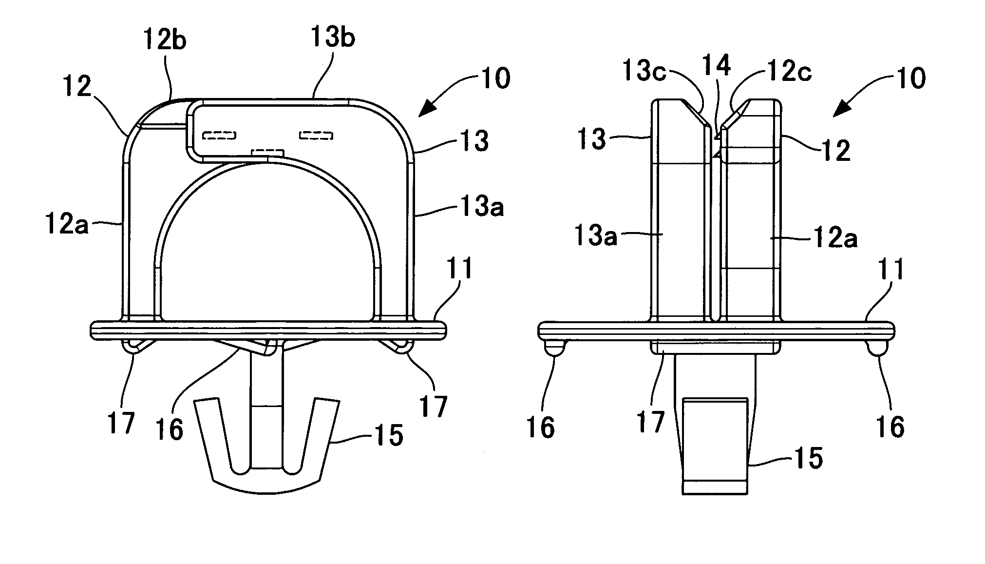
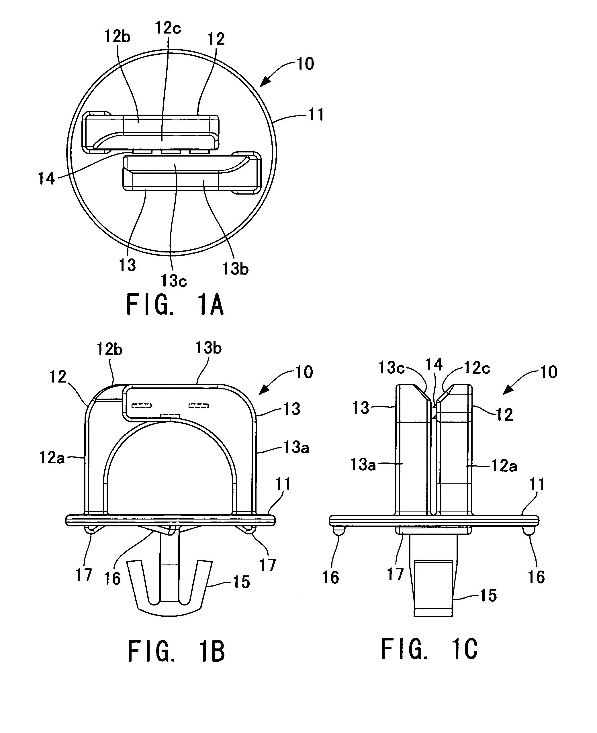
[0026]FIGS. 1A, 1B, and 1C are views showing the construction of a cable clamp according to an embodiment of the present invention, wherein FIG. 1A is a plan view of the cable clamp; FIG. 1B is a front view of the cable clamp; and FIG. 1C is a right side view of the cable clamp. The cable clamp 10 includes a pair of cable-holding bodies 12 and 13 secured to a base 11. The cable-holding bodies 12 and 13 each have an inverted L-shape or an arcuate shape and are respectively comprised of pillar portions 12a and 13a vertically extending from the base 11, and cantilever portions 12b and 13b extending from respective ends of the pillar portions 12a and 13a remote from the base 11, in respective directions substantially at right angles to the pillar portions 12a and 13a.

[0027]The above pair of cable-holding bodies 12 and 13 are arranged to extend in opposite directions suc...


PUM


Abstract

A cable clamp which is capable of preventing even a very fine cable to be treated from coming off or extending off therefrom, without any fear of the cable being damaged or broken, and is easy to carry out a clamping treatment and an extra length-bunching treatment on cables, with enhanced workability. The cable clamp includes a pair of cable-holding bodies each including a pillar portion vertically extending from the base, and a cantilever portion extending from an end of the pillar portion, remote from the base, in a direction substantially at right angles to the pillar portion. The pair of cable-holding bodies are configured such that the pillar portions are arranged to extend in opposite directions, with one of respective side surfaces of the respective cantilever portions being opposed to the other with a predetermined space therebetween.

Description

CROSS-REFERENCE TO RELATED APPLICATIONS[0001]This application is based upon and claims the benefits of priority from the prior Japanese Patent Application No. 2006-082266, filed on Mar. 24, 2006, the entire contents of which are incorporated herein by reference.BACKGROUND OF THE INVENTION[0002]1. Field of the Invention[0003]This invention relates to a cable clamp for holding cables in communication equipment and electronic equipment, and more particularly to a cable clamp suitable for clamping very fine cables.[0004]2. Description of the Related Art[0005]Recently, an increase in channel capacity is being demanded of communication equipment and electronic equipment. Further, the thickness of transmission cables installed in the equipment has been decreased according to the progress of manufacturing techniques. Particularly, in the communication equipment, to provide a high-speed and stable communication quality, optical transmission using optical fiber cables has been becoming domina...

Claims


Application Information

Patent Timeline
Patent Type & Authority Patents(United States)
IPC IPC(8): F16B15/00
CPCG02B6/4471H02G3/30H02G3/32G02B6/4452
Inventor KUSUDA, KIYONORISATO, HISATO
Owner FUJITSU LTD
Why Eureka
Try Eureka