Expansible chamber pneumatic system

a pneumatic system and expansion chamber technology, applied in the direction of positive displacement liquid engine, piston pump, non-mechanical valve, etc., can solve the problem of wasting hp air

Active Publication Date: 2009-05-05
PSG CALIFORNIA LLC
View PDF30 Cites 52 Cited by
  • Summary
  • Abstract
  • Description
  • Claims
  • Application Information

AI Technical Summary

Benefits of technology

[0008]In summary, this invention is an expansible chamber pneumatic system, for example a fluid pump system, including two or more double-acting diaphragm pumps (or one pump utilizing Process air more than once), each with symmetrical left and right pump housings, each housing including an air chamber and a fluid chamber separated by a movable diaphragm. The diaphragms are connected for reciprocating movement in unison to pump fluid through their respective fluid chambers. Each pump includes an air direction control (DC) valve actuated by Control air to direct Process air alternately into right and left air chambers, simultaneously releasing used Process air from the other air chamber to thereby move the pistons to pump fluid. A pilot valve is responsive to pistons reaching their travel limits to direct Control air to the DC valve, alternating the directions of Process air flow through the DC valve to reverse the movement of the pump pistons. Control air exhausts through the pilot valve to atmosphere. Process air exhausts through the DC valve from one pump to become input or motive air for the next pump.

Problems solved by technology

The problem with prior art systems as just described is that HP air is being wasted by putting it through a reducing valve to lower its pressure, wasting also the energy used to generate the HP air in the first place.

Method used


Image

  • Expansible chamber pneumatic system
  • Expansible chamber pneumatic system
  • Expansible chamber pneumatic system

Examples


Embodiment Construction

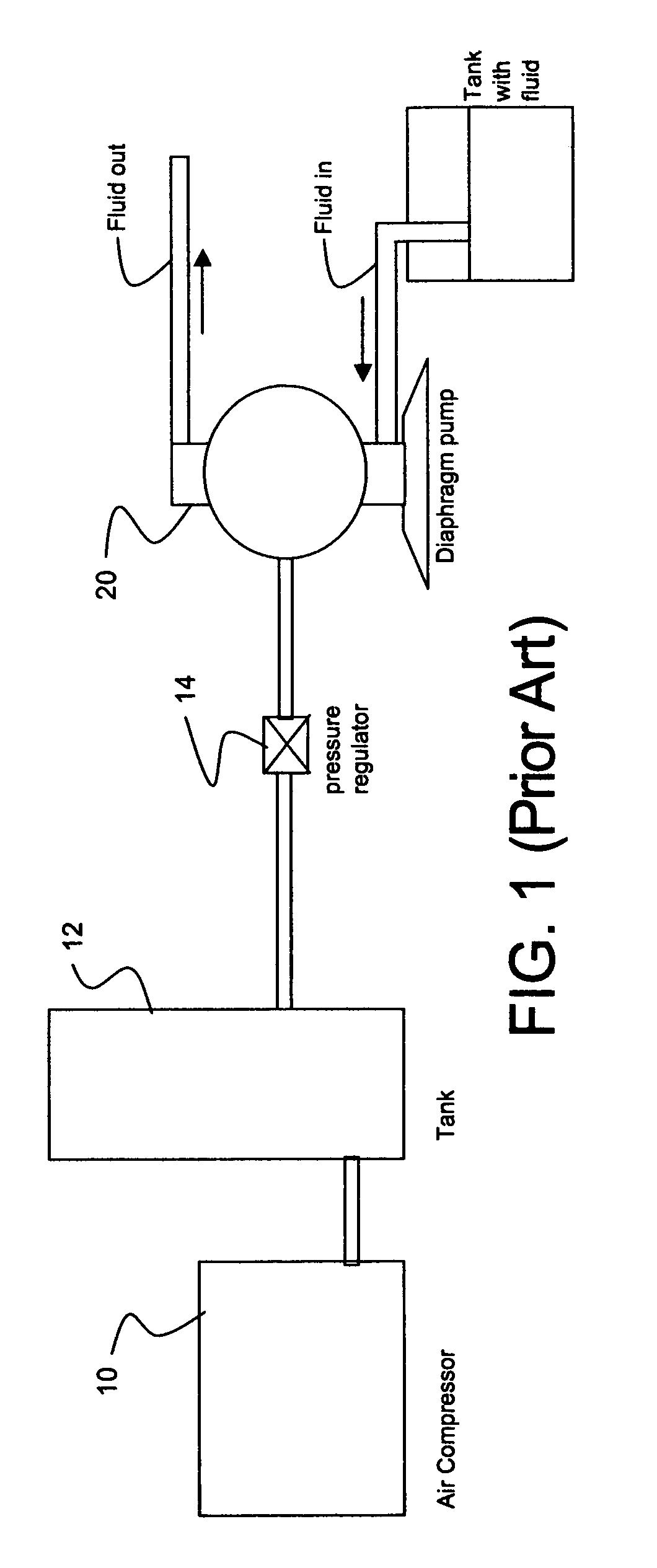
[0015]FIG. 1 represents a prior art system in which a compressor 10 delivers 100 psig air to a tank 12, and is distributed from the tank 12 through plant piping. A diaphragm pump 20 requires input or motive air at 50 psig. A pressure regulator 14 upstream of the pump 20 reduces the motive air pressure from 100 psig to 50 psig to operate the pump 20. To the extent that motive air is distributed to pump(s) 20, 25% of the compressor energy put into that quantity of air is wasted.

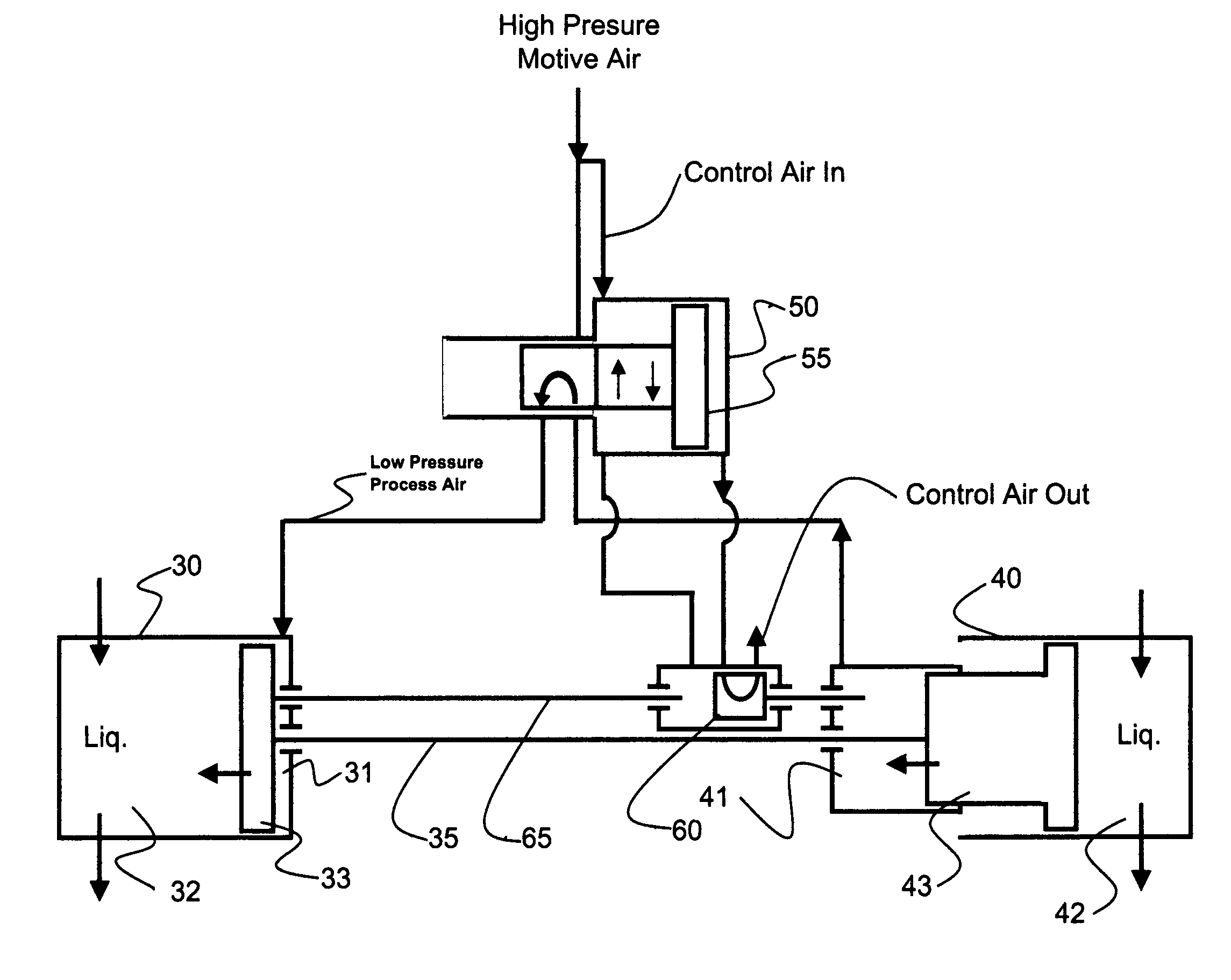
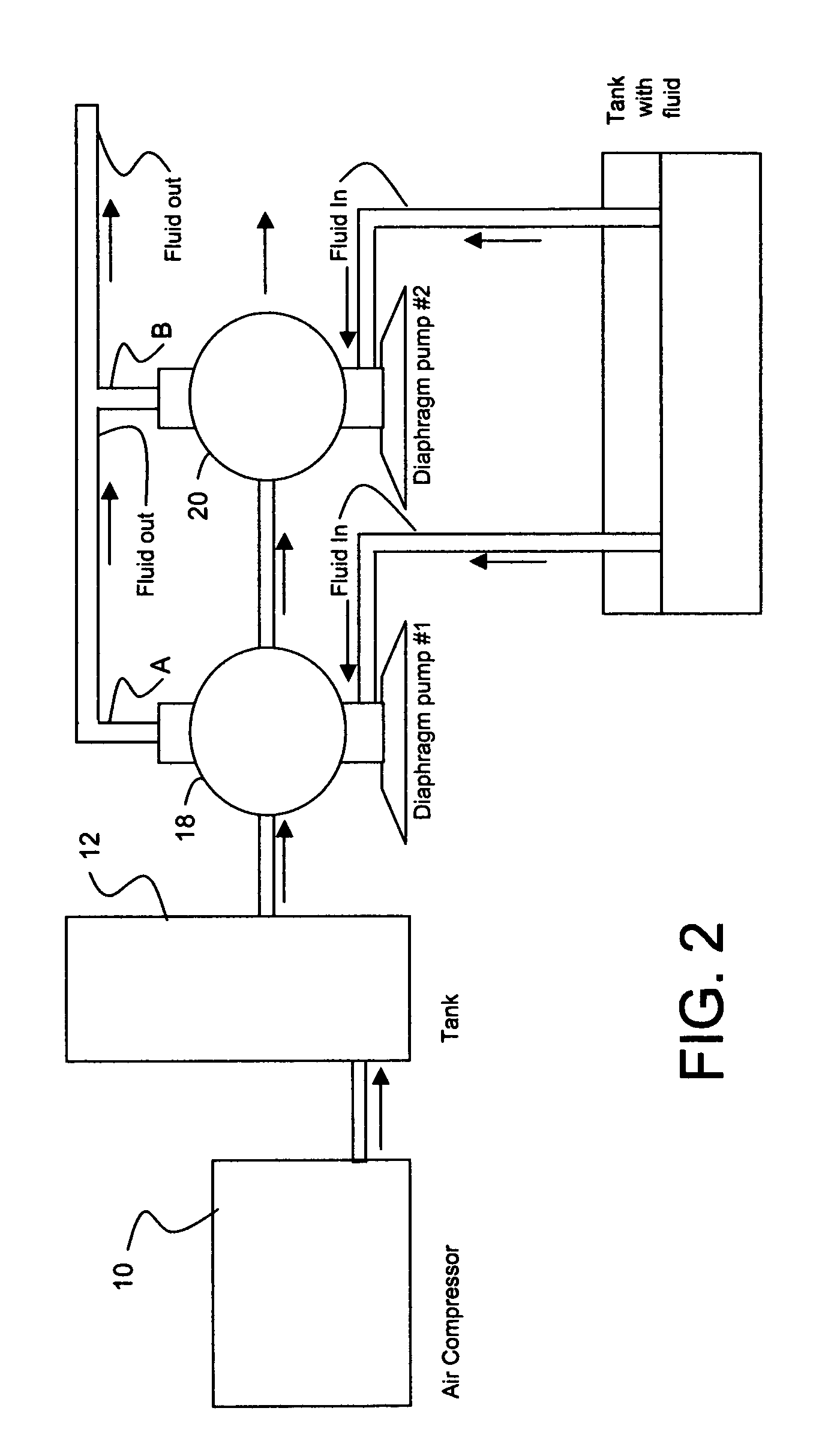
[0016]In FIG. 2, the system of this invention includes a compressor 10, tank 12, a first diaphragm pump 18, and a second diaphragm pump 20. (Unlike the prior art system of FIG. 1, the FIG. 2 system of this invention does not include a pressure regulator). The pumps 18, 20 are pneumatically connected in series. HP motive air enters pump 18 at 100 psig to produce output fluid flow A. Process air exhausted from pump 18 at 50 psig enters pump 20 as motive air. Pump 20 in turn generates fluid flow B, exhausts its Pr...


PUM


Abstract

An expansible chamber pneumatic system, for example a fluid pump system, includes two or more double-acting diaphragm pumps, each with symmetrical left and right pump housings, each housing including an air chamber and a fluid chamber separated by a movable diaphragm. The diaphragms are connected for reciprocating movement in unison to pump fluid through their respective fluid chambers. Each pump includes an air valve actuated by Control air to direct Process air into one of the air chambers, simultaneously releasing used Process air from the other air chamber to thereby move the diaphragms, thereby to pump fluid. A pilot valve directs Control air to the air valve to position the air valve. The pilot valve is responsive to diaphragms reaching their travel limit in one direction to direct Control air to reverse the directions of Process air flow through the air valve to thereby reverse the movement of the pump diaphragms. Control air exhausts through the pilot valve to atmosphere. Process air exhausts through the air valve from one pump to become input or motive air for the next pump.

Description

CROSS-REFERENCE TO RELATED APPLICATION[0001]My related Provisional Patent Application No. 60 / 629,097 was filed on Nov. 18, 2004. That filing date is claimed for this application.BACKGROUND OF THE INVENTION[0002]High pressure shop air, or “HP air” is typically at about 125 psig pressure. Air is pressurized in a compressor and stored in a tank for operation in a range of, typically, 115 to 125 psig. HP air from the tank is piped throughout the plant as motive air for pneumatic equipment, or as pressurized air for purposes such as spraying or cleaning. While “high pressure” has to be high enough to meet all pressure requirements, some equipment operates at pressures lower than the “high pressure” level. For such lower pressure applications, a pressure reducing valve is required upstream of the equipment to reduce the pressure input to such equipment. A pressure reducing valve is a modulating orifice which allows high pressure air to expand to a lower pressure.[0003]The problem with pri...

Claims


Application Information

Patent Timeline
Patent Type & Authority Patents(United States)
IPC IPC(8): F04B43/06
CPCF04B25/005F04B43/06F04B43/0736
Inventor GLAUBER, CARL J
Owner PSG CALIFORNIA LLC
Why Eureka
Try Eureka