Apparatus and method for estimating a channel

a channel estimation and channel technology, applied in the field of telecommunications, can solve the problems of huge computational complexity at the receiver, new challenges for channel estimation, and may not be suitable for mass-market mobile receivers, and achieve the effect of reducing complexity

Active Publication Date: 2009-05-05
DOCOMO COMM LAB EURO +1
View PDF5 Cites 9 Cited by
  • Summary
  • Abstract
  • Description
  • Claims
  • Application Information

AI Technical Summary

Benefits of technology

[0044]It is an object of the present invention to provide an improved concept for channel estimation with reduced complexity.
[0050]The present invention is based on the finding that a channel estimation scheme based on Fourier transform can be simplified by efficiently exploiting the properties of the Fourier transform. In particular, it has been found that a transform based on a Fourier transform, for example a Fourier transform or an inverse Fourier transform, provides an estimated channel impulse response of a communication channel extending from a transmitting point of a plurality of transmitting points to a receiving point, if the transmitting points transmit different pilot sequences for channel estimation at the receiving point. In particular, if the pilot sequences are orthogonal and phase shifted to each other, then a transform based on a Fourier transform directly provides an estimated channel response of a channel to be estimated.
[0055]While the estimator disclosed by Li at al. requires a plurality of additional Fourier transforms in order to compute the intermediate values required for the channel estimation scheme, only one IDFT operation per communication channel is required in order to estimate the channel impulse response which simplifies the receiver structure and reduces the complexity of the inventive channel estimation scheme. Moreover, the improvement of the proposed receiver structure compared to the prior art receiver structure has no negative effects on the performance of the channel estimator.
[0057]Additionally, the inventive channel estimation scheme is simplified in comparison with the prior art channel estimation schemes since the transformed signal already contains an estimate of the channel impulse response to be estimated. Therefore, no matrix inversions or matrix by vector multiplications are necessary which further reduces the complexity of the receiver structure.
[0058]Moreover, the inventive channel estimation scheme can be applied to any of orthogonal sequences having different phase shifts to each other provided that these phase shifts are known at the receiving point, since the respective transformer for providing a particular channel's estimate can efficiently be adjusted to the phase shift of the pilot sequence transmitted through the channel to be estimated.

Problems solved by technology

This implies new challenges for channel estimation.
While the separation of the signals corresponding to several transmitting points, each of them having a transmit antenna, is a challenging task, the extension from a receiver having one antenna to a system with several receive antennas is straight forward, as long as the signals are mutually uncorrelated.
Although the pilot symbols described in the above-cited prior art allow an accurate channel estimation, an enormous computational complexity at the receiver is required in order to perform matrix inversions required by the channel estimation algorithm.
Due to this high computational complexity, the estimation scheme described in the above prior art document cannot be implemented at low cost, so that the disclosed algorithm may not be suitable for mass-market mobile receivers.
However, the complexity of this approach is enormous since the singular value decomposition has to be calculated.
However, due to a difficulty of obtaining perfect orthogonality between training sequences, matrix inversions may be necessary.
Additionally, if the training sequences are non-orthogonal, then the channel estimation scheme proposed by Li becomes more complex since the paths corresponding to the communication channels cannot be separated in straight forward way.

Method used


Image

  • Apparatus and method for estimating a channel
  • Apparatus and method for estimating a channel
  • Apparatus and method for estimating a channel

Examples


Embodiment Construction

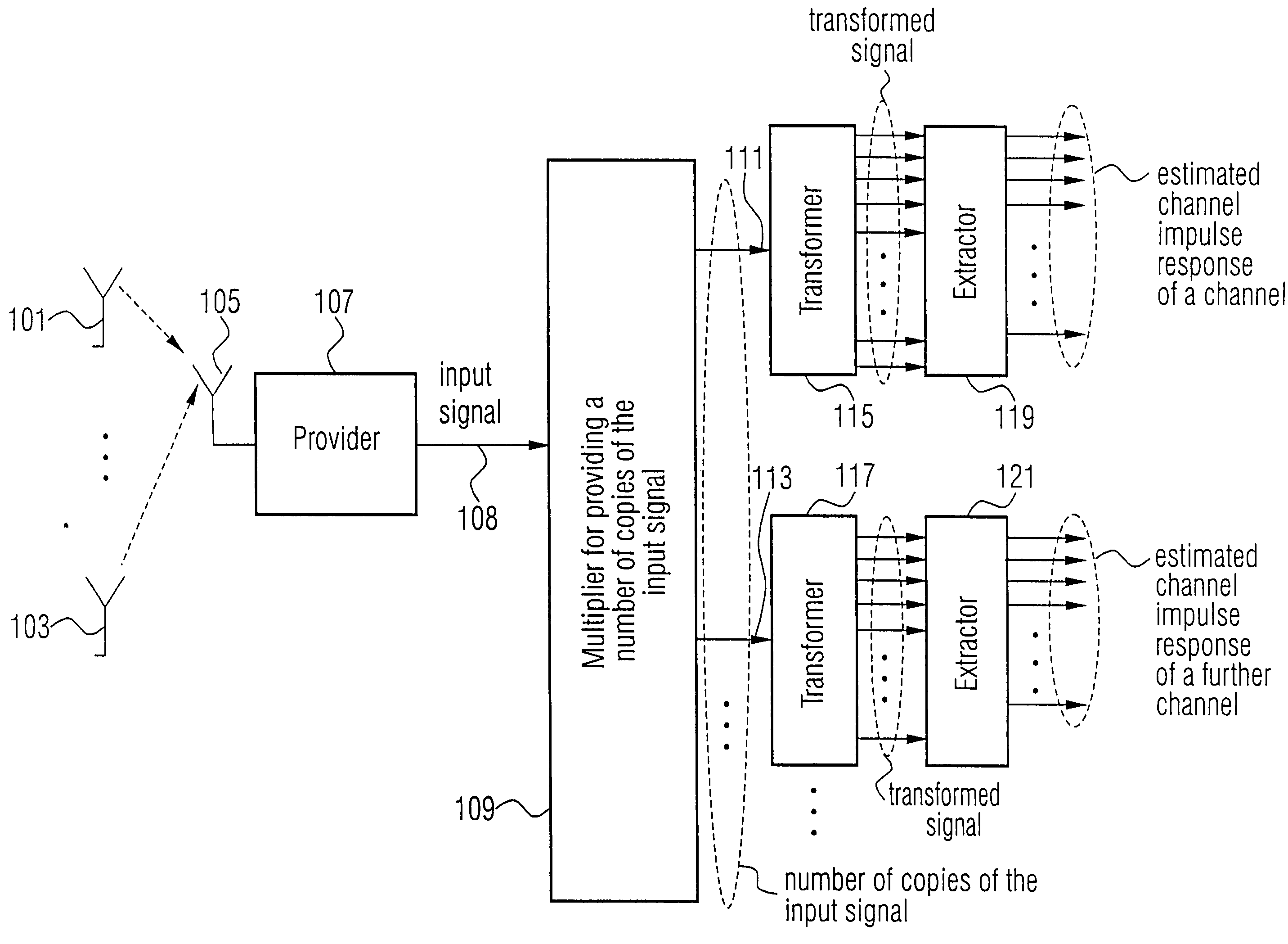
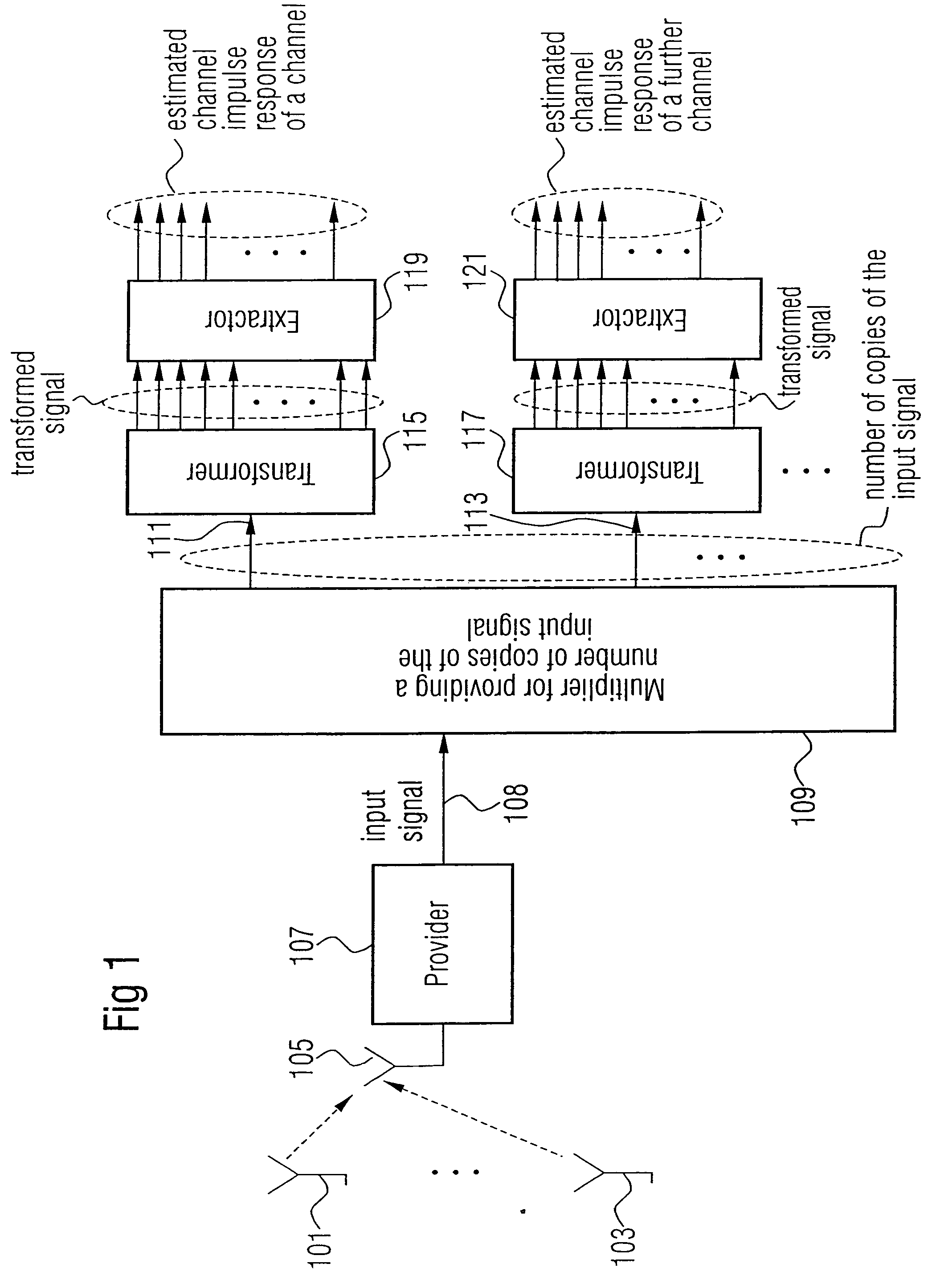
[0067]In FIG. 1 a block diagram of an inventive apparatus for estimating a channel is shown, wherein the apparatus is embedded in a multiple output scenario characterized by a plurality of transmit antennas. For the sake of clarity FIG. 1 shows only two transmit antennas, 101 and 103.

[0068]The apparatus shown in FIG. 1 comprises a receive antenna 105 having an output connected to a provider 107. The provider 107 has an output connected to a multiplier 109 for providing a number of copies of the input signal. The multiplier 109 has a number of outputs, the number corresponding to a number of copies to be provided or, in other words, corresponding to a number of transmitting points. For the sake of simplicity, only an output 111 and a further output 113 of the multiplier 109 are depicted in FIG. 1.

[0069]The output 111 is connected to a transformer 115, and the further output 113 is connected to a transformer 117. Each of the transformers 115 and 117 has a number of outputs correspondi...


PUM


Abstract

An apparatus for estimating a channel from a transmitting point to a receiving point in an environment, in which at least two transmitting points spaced apart from each other are present, the transmitting point having associated therewith a pilot sequence, wherein the pilot sequences are different from each other, having a provider for providing an input signal, the input signal including a superposition of signals from the transmitting points, a multiplier for providing a number of copies of the input signal, the number of copies being equal to the number of transmitting points, for each copy of the input signal, a transformer for transforming the copy or a signal derived from the copy to obtain a transformed signal, the transformer being operative to apply a transform algorithm which is based on a Fourier transform, and for each transformed signal, an extractor extracting a portion of the transformed signal.

Description

CROSS-REFERENCE TO RELATED APPLICATION[0001]This application is a continuation of copending International Application No. PCT / EP03 / 05376, filed May 22, 2003, which designated the United States, and is incorporated herein by reference in its entirety.BACKGROUND OF THE INVENTION[0002]1. Field of the Invention[0003]The present invention is in the field of telecommunications and, in particular, in the field of channel estimation in a multiple input scenario, in which a receiver receives signals from more than one transmitting antenna.[0004]2. Description of the Related Art[0005]The steadily-increasing demand for high data rates necessary for today's and future mobile radio applications require high data rate techniques efficiently exploiting the available band width or, in other words, the achievable channel capacity. Therefore, multiple input multiple output (MIMO) transmission systems have achieved considerable importance in recent years. MIMO systems employ a plurality of transmittin...

Claims


Application Information

Patent Timeline
Patent Type & Authority Patents(United States)
IPC IPC(8): H04L1/02H04B3/00H04J99/00H04L1/06H04L25/02H04L27/26
CPCH04L1/06H04L25/0204H04L25/022H04L25/0224H04L25/024H04L27/2647
Inventor AUER, GUNTHER
Owner DOCOMO COMM LAB EURO
Why Eureka
Try Eureka