Flow rate measuring apparatus

a technology of flow rate measurement and measuring apparatus, which is applied in the direction of volume/mass flow measurement, measurement devices, instruments, etc., can solve the problems of increasing pressure loss, generating errors in flow rate measurement apparatus, etc., and achieves the reduction of flow rate measurement errors, prolonging the projection period, and improving durability and service life

Active Publication Date: 2009-05-12
MITSUBISHI ELECTRIC CORP
View PDF32 Cites 23 Cited by
  • Summary
  • Abstract
  • Description
  • Claims
  • Application Information

AI Technical Summary

Benefits of technology

[0009]The present invention aims to solve the above problems in the related art and provides a flow rate measuring apparatus enabling accurate flow rate measurement and also enabling pressure loss occurring due to plugging into a main passage to be reduced particularly when used to measure intake air flow rate in an automotive internal-combustion engine by suppressing changes in flow velocity inside a measuring passage even if frequencies of pulsating flow synchronized with rotational frequency of the internal-combustion engine differ and flow velocity distribution inside the main passage differs while also preventing foreign matter such as dust, etc., contained in intake air to the internal-combustion engine from striking a flow rate detecting element at high speed and also ensuring effects enabling durability and service life to be improved.
[0011]According to the present invention, because the first bend portion and the second bend portion which bend the flow channel by approximately 90 degrees are disposed in the passage extending from the inflow aperture to the third passage in which the flow rate detecting element is disposed, foreign matter such as dust, etc., in the measured fluid strikes the first bend portion and the second bend portion and is decelerated. Thus, even if foreign matter strikes the flow rate detecting element, its collision energy is small, improving durability and service life of the flow rate detecting element.
[0012]Because the inflow aperture and the outflow aperture of the measuring passage are positioned in close proximity to each other in a radial direction of the main passage, even if the rotational frequency changes and the flow velocity distribution inside the main passage changes despite the amount of intake air being equal, differences in flow velocity are less likely to occur in the vicinity of the inflow aperture and the outflow aperture of the measuring passage. Thus, differences are less likely occur in the flow velocity of the flow of the measured fluid that is induced inside the measuring passage, enabling flow rate measurement errors to be reduced.
[0013]In addition, because the inflow aperture and the outflow aperture of the measuring passage are positioned in close proximity to each other in the radial direction of the main passage, length of projection of the flow rate measuring apparatus in a radial direction of the main passage can be shortened, enabling pressure loss inside the main passage occurring due to plugging in to be reduced.

Problems solved by technology

Thus, when conventional flow rate measuring apparatuses are used in automotive internal-combustion engines, since the radial flow velocity distribution in the main passage varies depending on the rotational frequency of the internal-combustion engine even if the flow rate of the intake air flowing through the main passage is equal, differences arise between flow velocities in the vicinities of the inflow aperture and the outflow aperture of the bypass passage due to changes in the rotational frequency despite the amount of intake air being equal, giving rise to differences in the flow velocity of the flow that is induced inside the bypass passage, thereby generating errors in detected flow rate in the flow rate measuring apparatus.
Furthermore, when conventional flow rate measuring apparatuses are used in automotive internal-combustion engines, it is necessary for at least the inflow aperture and the outflow aperture to project inside the main passage, increasing projecting length in a radial direction of the main passage, thereby increasing pressure loss occurring due to the flow rate measuring apparatus being plugged into the main passage.

Method used


Image

  • Flow rate measuring apparatus
  • Flow rate measuring apparatus
  • Flow rate measuring apparatus

Examples


embodiment 1

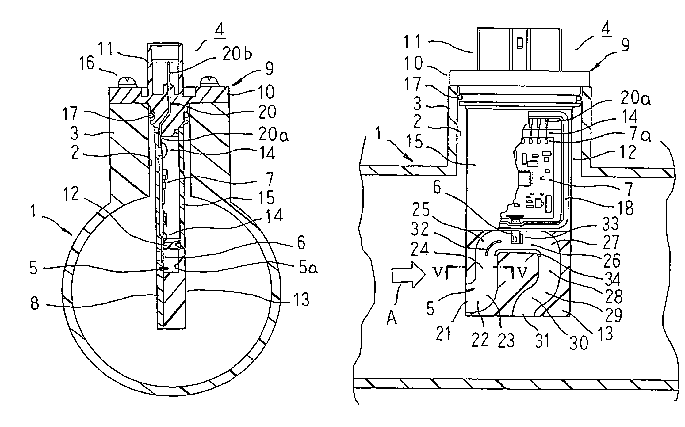
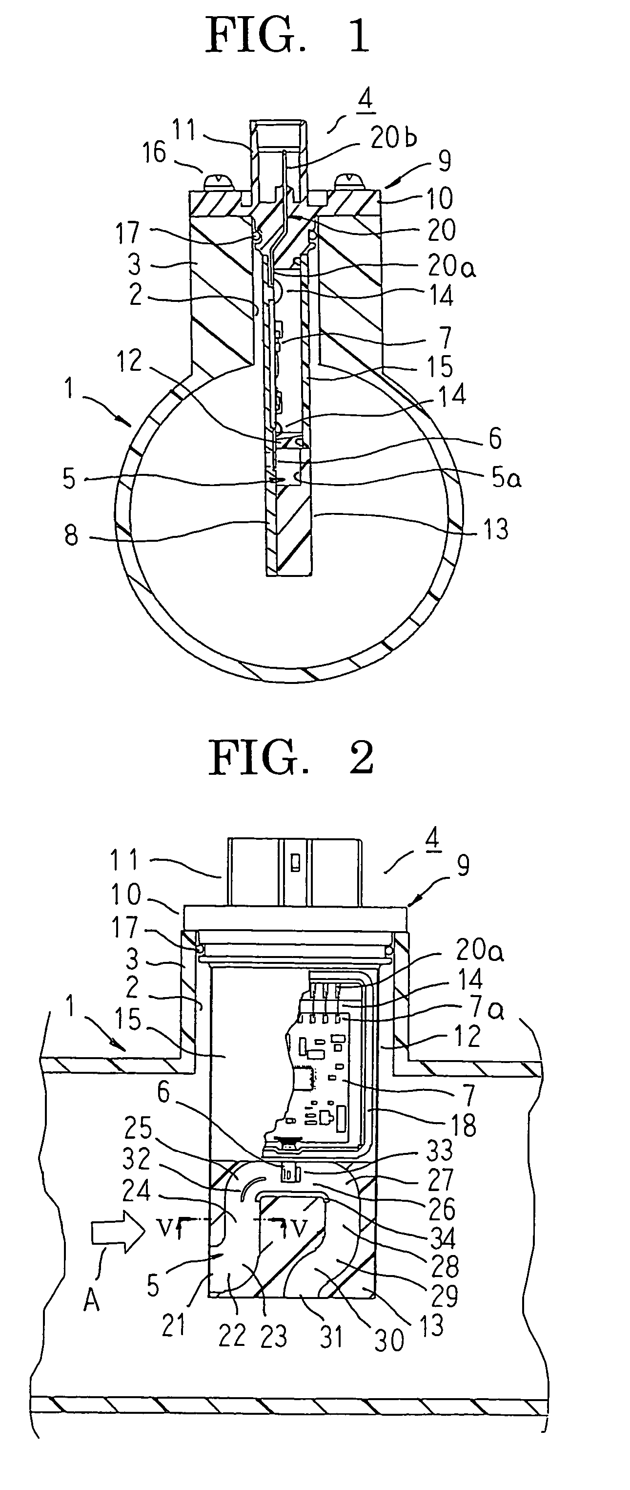
[0030]FIG. 1 is a lateral cross section showing a state in which a flow rate measuring apparatus according to Embodiment 1 of the present invention is mounted to a main passage, FIG. 2 is a partially cut-away side elevation showing part of the state in which the flow rate measuring apparatus according to Embodiment 1 of the present invention is mounted to the main passage, FIG. 3 is a partial enlargement showing a vicinity of a flow rate detecting element from FIG. 1, FIG. 4 is a partial enlargement showing a vicinity of the flow rate detecting element from FIG. 2, and FIG. 5 is a cross section taken along line V-V in FIG. 2 viewed in the direction of the arrows.

[0031]Moreover, here a “lateral cross section” means a cross sectional in a plane that is perpendicular to a central axis of the main passage. In FIG. 2, the main flow of the measured fluid flows in a direction indicated by arrow A in the figure.

[0032]In FIGS. 1 through 4, a main passage 1 is a cylindrical pipe body through ...

embodiment 2

[0068]FIG. 6 is a partially cut-away side elevation showing part of a state in which a flow rate measuring apparatus according to Embodiment 2 of the present invention is mounted to a main passage. Moreover, since lateral cross sections in each of the embodiments are similar to FIG. 1 in Embodiment 1 above, they will be omitted.

[0069]In FIG. 6, a measuring passage 5A includes: an inflow aperture 21, a first passage 22, a first bend portion 23, a second passage 24, a second bend portion 25A, a third passage 26A, a third bend portion 27A, a fourth passage 28A, a fourth bend portion 29A, a fifth passage 30, and an outflow aperture 31.

[0070]Outer peripheral wall surfaces of the second bend portion 25A, the third passage 26A, the third bend portion 27A, the fourth passage 28A, and the fourth bend portion 29A are formed into a continuous arc-shaped surface by increasing a radius of curvature of the outer peripheral wall surfaces of the second bend portion 25A, the third bend portion 27A, ...

embodiment 3

[0073]FIG. 7 is a partially cut-away side elevation showing part of a state in which a flow rate measuring apparatus according to Embodiment 3 of the present invention is mounted to a main passage.

[0074]In FIG. 7, a measuring passage 5B includes: an inflow aperture 21, a first passage 22, a first bend portion 23B, a second passage 24, a second bend portion 25B, a third passage 26, a third bend portion 27B, a fourth passage 28, a fourth bend portion 29, a fifth passage 30, and an outflow aperture 31.

[0075]Outer peripheral wall surfaces of the first bend portion 23B, the second bend portion 25B, and the third bend portion 27B are formed so as to have inclined surfaces in which a flat surface is inclined so as to deflect the measured fluid by approximately 90 degrees.

[0076]Moreover, the rest of this embodiment is configured in a similar manner to Embodiment 1 above.

[0077]In the flow rate measuring apparatus 4 according to Embodiment 1 above, if the radius of curvature of the first bend...


PUM


Abstract

A measuring passage includes: an inflow aperture opening onto a vicinity of an end portion of a surface of a main body portion that is perpendicular to a direction of flow of a main flow of a measured fluid so as to be facing upstream; and an outflow aperture opening onto an end surface of the main body portion in a direction of projection. A first passage extends from the inflow aperture in the direction of flow of the main flow to a first bend portion, a second passage extends from the first bend portion so as to be perpendicular to the direction of flow of the main flow toward the circuit housing portion to a second bend portion, a third passage extends from the second bend portion in the direction of flow of the main flow to a third bend portion, a fourth passage extends from the third bend portion in a direction that is perpendicular to the direction of flow of the main flow in a direction away from the circuit housing portion, and a fifth passage extends from the fourth bend portion in a reverse direction to the direction of flow A of the main flow and is connected to the outflow aperture.

Description

BACKGROUND OF THE INVENTION[0001]1. Field of the Invention[0002]The present invention relates to a flow rate measuring apparatus, and relates to an apparatus for measuring mass flow rate of air in an internal combustion engine, for example.[0003]2. Description of the Related Art[0004]Conventional flow rate measuring apparatuses include a bypass passage that bends a plurality of times from an inflow aperture to an outflow aperture, and a flow rate detecting element on which is formed a thermosensitive resistor constituted by a material such as platinum, etc., is disposed internally, and foreign matter such as dust, etc., contained in the measured fluid is decelerated and prevented from striking the flow rate detecting element at high speed by making the bypass passage bend a plurality of times. The outflow aperture of the bypass passage is disposed at a position that is further away from a circuit housing portion than the inflow aperture. (See Patent Literature 1, for example.)[0005]...

Claims


Application Information

Patent Timeline
Patent Type & Authority Patents(United States)
IPC IPC(8): G01F1/68
CPCG01F1/6842G01F1/68
Inventor URAMACHI, HIROYUKI
Owner MITSUBISHI ELECTRIC CORP
Why Eureka
Try Eureka