
Lateral thruster unit for marine vessels

a technology for marine vessels and thrusters, applied in marine propulsion, special-purpose vessels, vessel construction, etc., can solve the problems of difficult undocking, difficult to install, and difficult to maneuver a vessel in close quarters, and achieve the effect of convenient installation

Inactive Publication Date: 2009-05-12
HA DON DONGCHO
View PDF6 Cites 13 Cited by
  • Summary
  • Abstract
  • Description
  • Claims
  • Application Information

AI Technical Summary

Benefits of technology

[0019]This invention addresses the concerns and deficiencies as descried above associated with the prior art and presents an improved bow or stern thruster system. Accordingly, it is an objective of the present invention to provide a simple yet reliable self-contained thruster unit which may be easily installed without requiring the vessel to be hauled out of the water.

Problems solved by technology

The maneuvering of a vessel in close quarters as during docking and undocking is often challenging using only the vessel's main propulsion and steering systems.
It is especially difficult for those vessels equipped with an inboard engine with a single screw propulsion system and steered by an ordinary rudder.
In most cases, the rudders are configured for optimum performance within the structurally acceptable limits for the maximum operating speed intended for the vessel, and as a result, are often insufficient for adequate steering control at slow speeds.
The problem is compounded by the presence of a paddle-wheel phenomenon pronouncedly noticeable with such inboard single screw vessels, wherein the prop-wash created by the rotating propeller generates a swirling movement in the water below the hull to cause the stern of the vessel to drift sideways.
The steering control at slow speeds may prove further challenging if there are any prevailing wind or current conditions which may cause the bow and / or stern of the vessel to veer off from the intended course in an unpredictable manner.
However, piloting even these types of vessels in close quarters, especially the larger of these, many be challenging to all but the most experienced helmsmen, especially with presence of unfavorable wind and / or current conditions.
There are many problems associated with an internally mounted bow or stern thruster system.
First, these are costly to install.
However, the complexity and the cost involved with the installation of such are beyond the means of most pleasure vessel owners, and therefore, the use and the benefits of these devices are generally reserved only for the larger and expensive pleasure yachts or commercial vessels.
Second, the installation of the internal thruster unit potentially risks the degradation in the structural integrity in the bow and / or stern sections of the vessel.
The weakened structure may develop a failure as a result of navigating through the rough waters or from light bumps or collision with other vessels or the dock structure which otherwise may have been non-detrimental to a hull which had not been so modified.
Third, a structural crack or any failure in the below-the-waterline seal joint, including those seal joints integral to the thruster unit mechanism, will results in the water ingestion aboard the vessel.
The leakage aboard may take place while the operator is unaware, and if the rate of such leakage is greater than the rate at which the vessel's overboard pump system is able to discharge overboard the vessel may sink.
Fourth, the ducting will incur marine growth and, unless costly maintenance is performed regularly, result in reduced performance of the thruster system.
The access to clean the interior of the ducting and the gearbox portion of the drive unit within the ducting is difficult, because the accessibility thereto is inhibited by the propeller(s) and the narrowness of the passageway within the ducting.
For similar reasons, the maintenance repair is costly.
Fifth, because holes are created on both sides of the bow due to the ducting, the hydrodynamic effects reacting against the discontinuous surfaces on either side of the hull will generate resistance, and thus reduces the operating efficiency of the vessel.
Finally, yet importantly, the internally mounted system detracts from a valuable and limited usable onboard space within the hull.
However, both of these devices still have the disadvantages of costly hull modification and installation, possible reduction in the structural integrity of the hull, and mechanical complexity resulting from the incorporation of the retracting system.
However, the drawback of the Roestenberg is mechanical complexity and delicate nature of the pivotal retracting mechanism, which may easily incur damage while the vessel is navigating through rough waters.
However, the Pinsof's stern thruster has a disadvantage of mechanical complexity associated with the linear or rotary deployment and retracting mechanism employed thereby.
While Wardell, Van Breems, Roestenberg, and Pinsof all cite the advantages of incorporating retractability feature to their thruster systems, it is noted that there are also disadvantages associated with the same.
A sustained dry operation of the thruster while the thruster unit is out of the water may lead to premature failures of the drive shaft seal(s) or the motor.
In addition, the operator must retract the thruster unit out of the water prior to commencing high-speed cruise, or the hydrodynamic forces may cause damages to the drive unit and its support structure.
However, incorporating such safety features will increase complexity and cost and decrease the overall reliability of the thruster system.

Method used


Image

  • Lateral thruster unit for marine vessels
  • Lateral thruster unit for marine vessels
  • Lateral thruster unit for marine vessels

Examples


Embodiment Construction

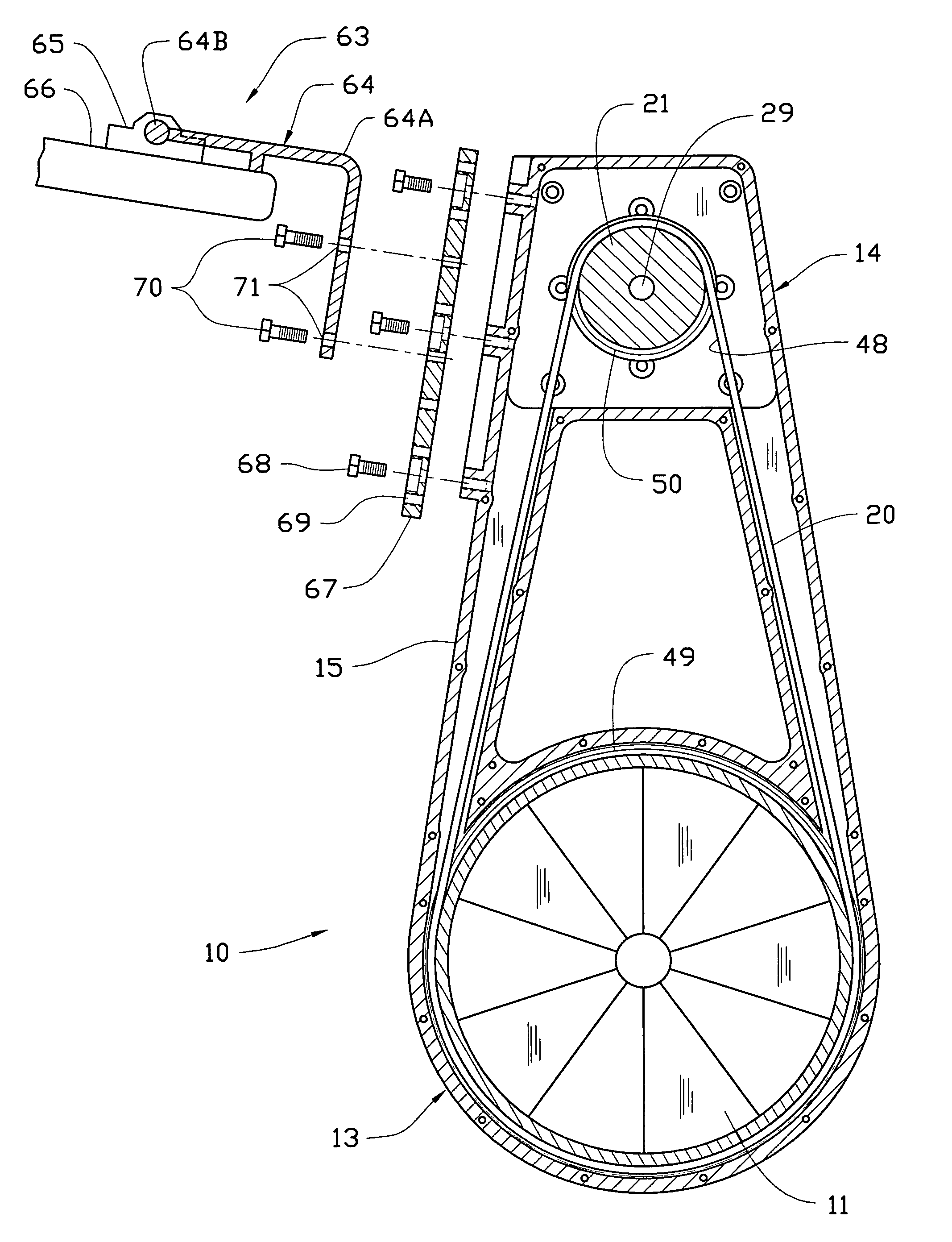
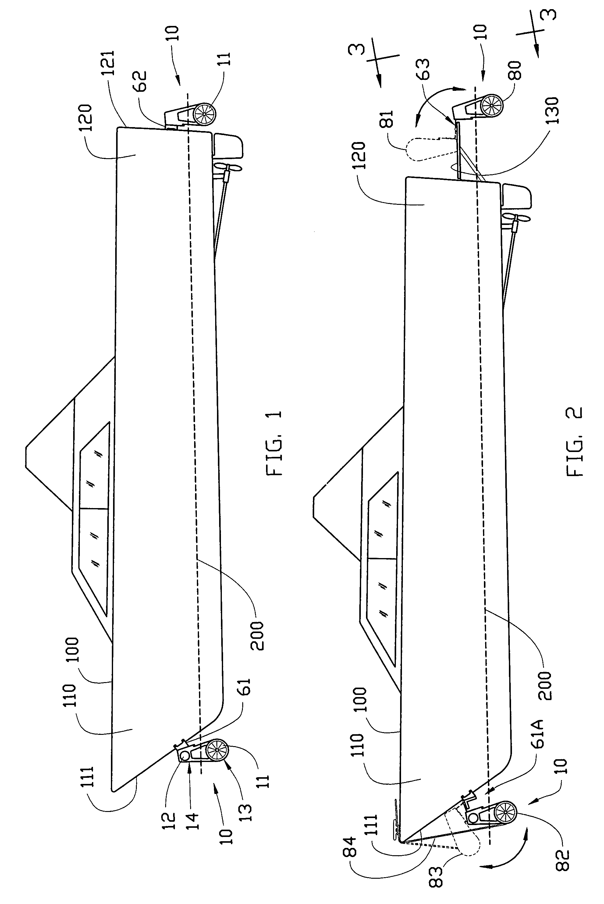
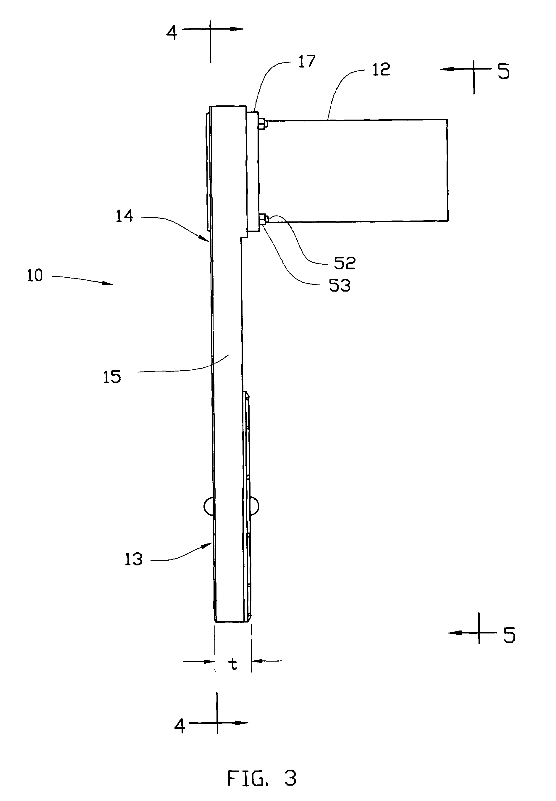
[0045]FIGS. 1-8 of the drawing illustrate various aspects of a thruster unit 10 constructed according to the present invention. Referring to FIG. 1, a vessel 100 is illustrated with the thruster unit of the present invention 10 mounted on the stern 111 at the bow 110 and on the transom 121 at the stern 120 thereof. The illustrated vessel in FIG. 1 is a typical modern powered watercraft in the 25-30 feet range with an inboard-engine-driven single screw propulsion system with an ordinary rudder for steering. However, as already mentioned, the thruster unit 10 of the present invention may be conveniently installed about the stern and / or on the transom of any kind and size of vessel. The present invention is equally adaptable for mounting onto a vessel with a swim platform 130 or any substantially horizontal area extending rearward of stern as shown in FIG. 2.

[0046]FIG. 1 shows the thruster unit 10 fixedly mounted in a normal, installed position with respect to the vessel with the lower...


PUM


Abstract

A thruster unit for generating side thrust for improved maneuverability of a marine vessel employs a peripherally-driven propeller situated below the waterline and remotely powered by a motor situated above the waterline via a flexible drive member. The propeller is supported by a rolling element bearing disposed circumferentially around the outer perimeter of the propeller providing both axial and radial support. The lower portion disposed for submerged operation has a substantially thin cross section with a narrow thickness aligned transversely to the vessel to operate hydro-dynamically while the vessel is underway. This makes it possible for the present invention to remain in the operating position indefinitely even while the vessel is in motion without risking a structural damage. The thruster unit can be installed on the vessel using a hinged bracket assembly such that during the extended periods while the vessel is not operating the thruster unit may be pivoted out from the water for dry storing, safely away from the corrosion, marine growth, or any other harmful effect of the water.

Description

REFERENCES CITED[0001]6,964,590November 2005Ha6,672,236January 2004Pinsof6,458,004October 2002Van Breems6,009,822January 2000Aron5,435,763July 1995Pignata5,140,926August 1992Denston4,807,552February 1989Fowler4,732,104March 1988Roestenberg4,294,186October 1981Wardell1,288,106December 1918Medynski  598,424February 1898KussCROSS-REFERENCE TO RELATED APPLICATIONS[0002]Not applicable.BACKGROUND OF THE INVENTION[0003]1. Technical Field[0004]This invention relates to a lateral thruster unit externally mounted at the bow, the stern, or the swim platform of a marine vessel for improving the slow speed maneuvering thereof, more particularly to such thruster unit which is capable of remaining in the operating position while the vessel is in motion without incurring a structural damage.[0005]2. Description of the Related Art[0006]The maneuvering of a vessel in close quarters as during docking and undocking is often challenging using only the vessel's main propulsion and steering systems. It is...

Claims


Application Information

Patent Timeline
Patent Type & Authority Patents(United States)
IPC IPC(8): B63H1/16
CPCB63H25/46B63H1/16B63H5/125B63H20/08B63H25/42B63H2023/005B63H2023/0225
Inventor HA, DON DONGCHO
Owner HA DON DONGCHO
Learn More