
Method for explosive bonding of tubular metal liners

Active Publication Date: 2009-05-12
HIGH ENERGY METALS
View PDF19 Cites 22 Cited by
  • Summary
  • Abstract
  • Description
  • Claims
  • Application Information

AI Technical Summary

Benefits of technology

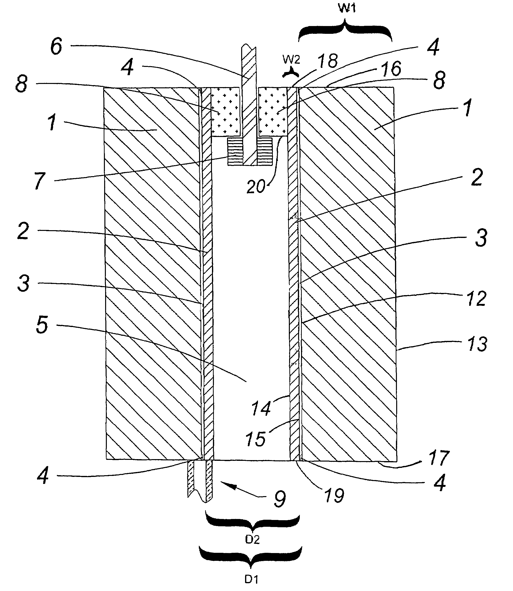
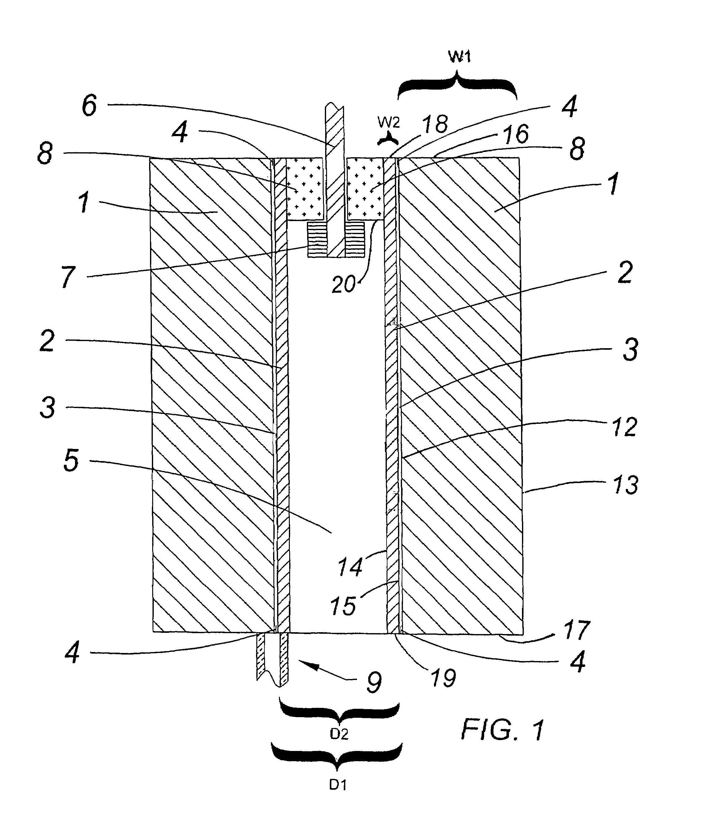
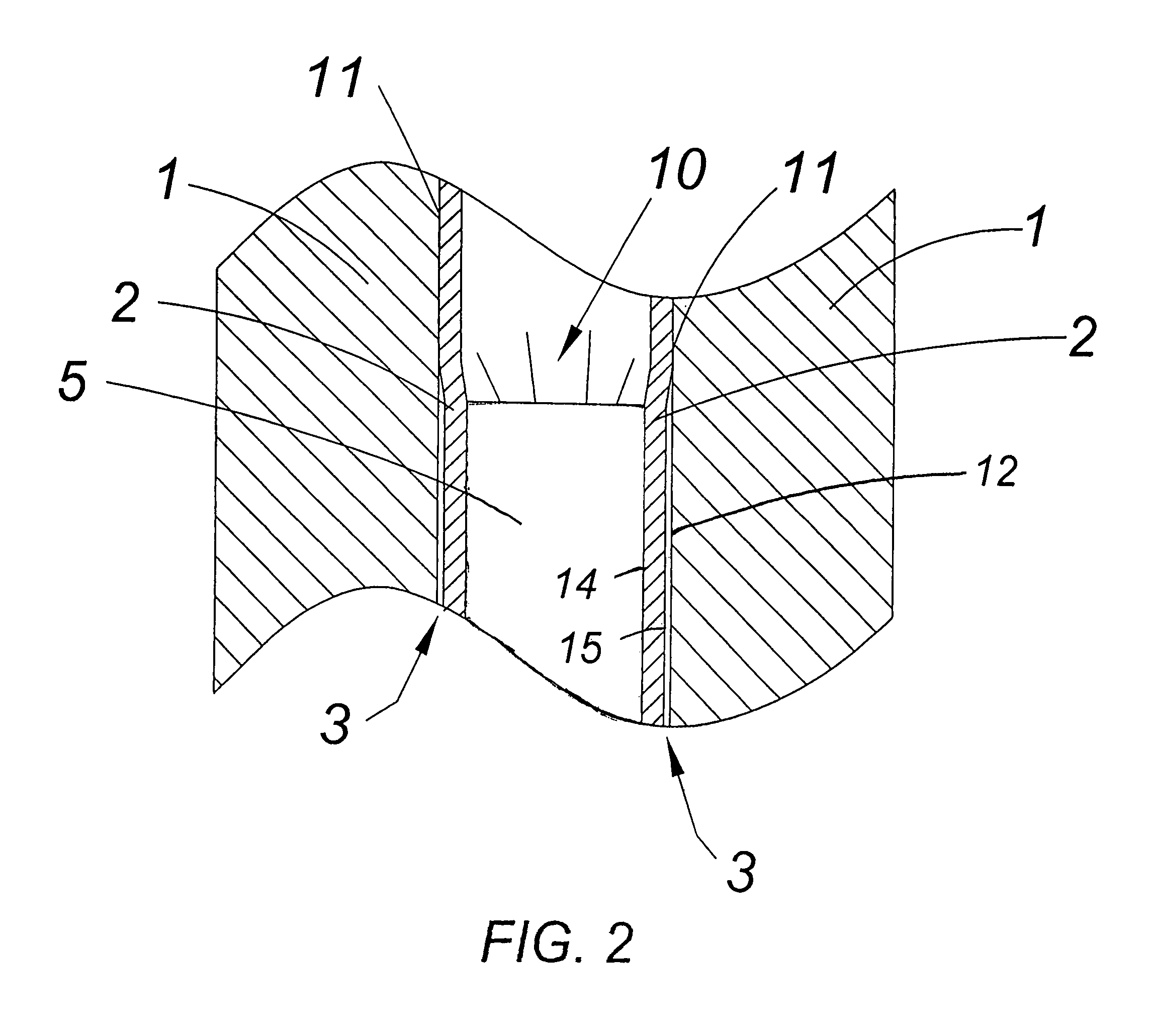
[0011]The detonation initiates an explosive front traveling uniformly down the internal surface of the smaller tube expanding the internal surface of the smaller tube with sufficient velocity to weld the smaller tube to the internal surface of the larger tube. A vacuum may be formed within the annular gap and / or gas(es) introduced therein to prevent build-up of excessive heat at the explosive front.

Problems solved by technology

The process of explosive welding has been adapted for the purpose of bonding coaxial tubes, but typically has been limited to using explosives to implode a larger tube onto a smaller tube.
Lengths of 60 inches (152.4 cm) have been achieved, but with significant difficulty and added expense.
Bonding longer length tubes is problematic due primarily to the difficulty in: 1) ensuring uniform density and detonation velocity of the explosive over the entire length of the tube; and 2) preventing excessive heat from accumulating at the surfaces that are being bonded as the air is pushed out between the two tubes during the explosive event.
The added heat can create resolidified melt pockets and intermetallics at the bonded joint which are typically brittle and degrade the quality of the joint.
In addition, variation in the forces at the detonation front of the explosives can create wrinkles and anomalies in the imploding larger tube as it collapses onto the smaller tube.
Such techniques are expensive, time-consuming and require specialized equipment.
Use of inserts or tools is expensive and requires a customized tool or insert to fit the size of metal tube involved.
Techniques involving inserts also are associated with the uneven transfer of energy to the tube to be bonded.

Method used


Image

  • Method for explosive bonding of tubular metal liners
  • Method for explosive bonding of tubular metal liners
  • Method for explosive bonding of tubular metal liners

Examples


Embodiment Construction

[0015]The following detailed description illustrates the invention by way of example, not by way of limitation of the scope, equivalents or principles of the invention. This description will enable one skilled in the art to perform the invention, and describes several embodiments, adaptations, variations, and alternatives.

[0016]In this regard, the invention is illustrated in the figures, and is of sufficient complexity that the many parts, interrelationships, and sub-combinations thereof cannot be fully illustrated in a single patent-type drawing. For clarity and conciseness, the drawings show in schematic, or omit, parts that are not essential in that drawing to a description of a particular feature, aspect or principle of the invention being disclosed. Thus, the best mode embodiment of one feature may be shown in one drawing, and the best mode of another feature will be called out in another drawing.

[0017]All publications, patents and applications cited in this specification are h...


PUM

PropertyMeasurementUnit
Fractionaaaaaaaaaa
Thicknessaaaaaaaaaa
Diameteraaaaaaaaaa

Abstract

An explosion welding method for metal tube liners in which a metal tube of smaller outside diameter is positioned coaxially within a metal tube of larger inside diameter with one or more shims inserted at opposed tube ends to form a uniform annular gap. The tubes are vertically positioned on a flat surface, and the smaller tube is filled with explosive material detonated from its top surface. The detonation initiates a uniform explosive front traveling down the smaller tube expanding the internal surface of the smaller tube with sufficient velocity to weld the tubes. A vacuum may be formed within the annular gap and / or gas(es) introduced therein to prevent build-up of excessive heat at the explosive front.

Description

CROSS REFERENCE TO RELATED APPLICATION[0001]This application claims priority under 35 USC 119(e) of Provisional Patent Application Ser. No. 60 / 771,081 filed Feb. 7, 2006, entitled “Method for Explosive Bonding of Tubular Metal Liners,” which is hereby incorporated by reference in its entirety.FIELD OF THE INVENTION[0002]The invention relates to the use of explosives to metallurgically weld a metal tube liner to the internal surface of a larger metal tube.BACKGROUND OF THE INVENTION[0003]Explosive welding of metals has been in practice commercially since the mid 1960's and involves the use of explosives to accelerate metals into each other with sufficient velocity and at an angle to allow a metallurgical joint to be created. The process is well suited to bonding flat sheets and plates together. Initially, the industry focused on creating products involving flat materials such as composite metal plates used for stamping coins and corrosive resistant metal composites for the chemical p...

Claims


Application Information

Patent Timeline
IPC IPC(8): B23K20/08
CPCB23K20/085B23K2201/06B23K2101/06
Inventor BRASHER, DAVID G.BUTLER, DONALD J.
Owner HIGH ENERGY METALS
Learn More