Apparatus and methodology for comminuting materials

a technology of comminuting materials and apparatus, which is applied in the direction of cocoa, grading, solid separation, etc., can solve the problems of reducing the efficiency of known throwing wheels, and consuming significant energy of jet mills, so as to improve construction and material flow characteristics, minimize energy loss for maximum acceleration of materials, and minimize eddies

Inactive Publication Date: 2009-05-12
AEROSION COMMINUTION SYST
View PDF37 Cites 3 Cited by
  • Summary
  • Abstract
  • Description
  • Claims
  • Application Information

AI Technical Summary

Benefits of technology

[0010]In embodiments of the invention, an improved comminuting apparatus comprises a throwing wheel having improved construction and material flow characteristics. An improved wheel enables use of particularly wear-resistant components only where required. Generally radially extending flow channels through the throwing wheel can be configured to minimize energy loss for maximum acceleration of the materials. The channels can converge towards the particle exits for minimizing eddies and the like.

Problems solved by technology

The aforementioned comminuting devices are energy intensive which can be related to a given particulate size.
Although jet mills can generate higher impact speeds than hammer and pin mills, the amount of energy jet mills consume can also be significant because they generate a jet of air to accelerate a particle, which typically requires a substantial amount of energy.
The known throwing wheels can suffer from inefficiencies in moving the particle to the wheel's periphery.
The harsh environment results in rapid erosion of components and as a result, and inherent in the dynamics of comminuting apparatus, imposes great challenges in maintaining integrity of the components and in driving and rotationally supporting such components.

Method used


Image

  • Apparatus and methodology for comminuting materials
  • Apparatus and methodology for comminuting materials
  • Apparatus and methodology for comminuting materials

Examples


Embodiment Construction

Generally

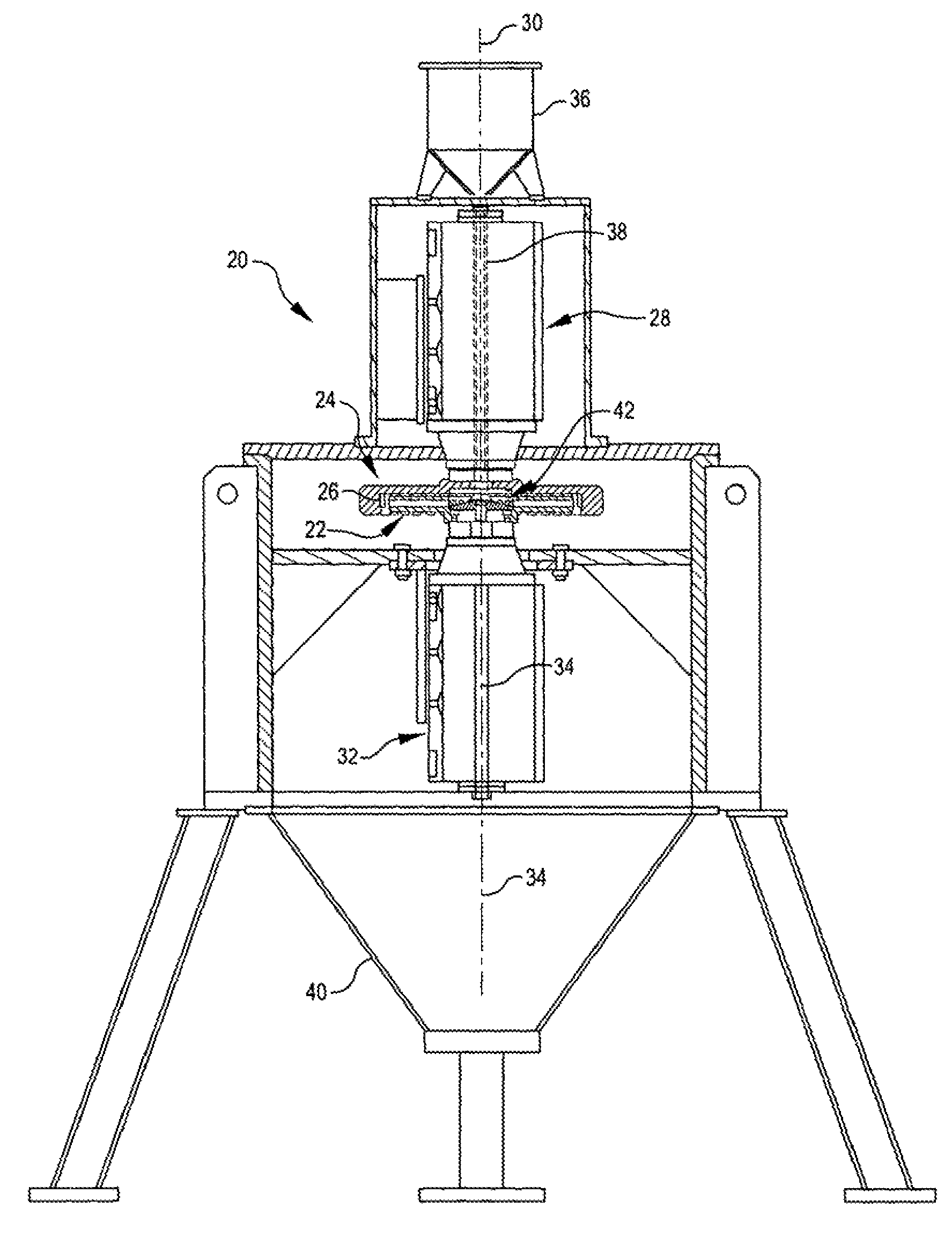
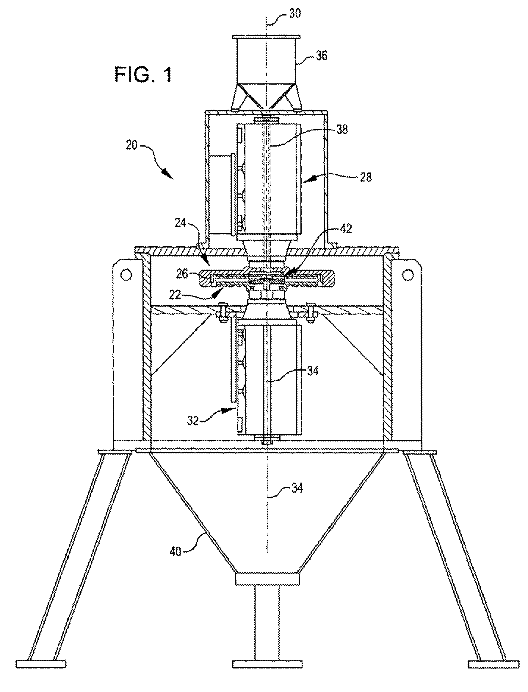
[0044]FIG. 1 is a partial cross-sectional view of a comminuting device 20 according to a first embodiment of the invention. This embodiment and exemplary variations therefrom and shown in FIGS. 2-9 are detailed in co-pending application Ser. No. 10 / 644,654, filed Aug. 20, 2004, now published as US 2004-0113002 A1, the entirety of which is incorporated herein by reference. FIGS. 1-9 and portions of the specification of Ser. No. 10 / 644,654 are reproduced herein to assist the reader.

[0045]As shown in FIG. 1, the comminuting device 20 includes a throwing wheel 22 to accelerate particles of material (omitted for clarity of the apparatus) toward an impact speed, and toward an impact rotor 24 that includes an impact surface 26 (see also FIG. 3) to fragment particles that collide with the impact surface 26 after exiting the throwing wheel 22. The comminuting device 20 also includes an impact motor 28 to rotate the impact rotor 24 about a rotor axis 30 and a throwing motor 32 to rot...


PUM


Abstract

A comminuting apparatus has a coaxial throwing wheel and impact rotor, the throwing wheel preferably comprising a plurality of channels for conducting particles from a central axis inlet to a plurality of particle exits to impact the impact rotor. The throwing wheel can be an assembly of wear-resistant inserts forming the channels. Flow channels through the throwing wheel can be configured, such as converging towards the particle exits to minimize energy loss during acceleration of the particles. Further, the comminuting apparatus can include a housing for ready access to the throwing wheel and impact rotor. A two-part housing is reversibly separable for accessing the comminuting chamber, throwing wheel and impact rotor within.

Description

CROSS REFERENCE TO RELATED APPLICATIONS[0001]This application is a Continuation-In-Part of the commonly owned U.S. patent application Ser. No. 10 / 644,654, filed Aug. 20, 2003, presently pending, which is hereby incorporated by reference in its entirety and which claims priority from commonly owned U.S. Provisional Patent Application No. 60 / 480,907, filed 23 Jun. 2003 which is hereby incorporated by reference in its entirety. Application Ser. No. 10 / 644,654 is also a Continuation-In-Part of the commonly owned U.S. patent application Ser. No. 10 / 042,052, filed 18 Oct. 2001, now abandoned, which is hereby incorporated by reference in its entirety.BACKGROUND OF THE INVENTION[0002]Many different types of material are comminuted for reducing the size of the particulates forms of the material. For example, coal excavated from a mine is frequently comminuted to make the particulate size smaller and more uniform to facilitate the coal's transportion and / or to provide consistent combustion in...

Claims


Application Information

Patent Timeline
Patent Type & Authority Patents(United States)
IPC IPC(8): B02C19/00
CPCB02C13/1814B02C19/0025B02C2013/1857
Inventor TESSIER, LYNNGRAHAM, JAMES B.GRAHAM, RUSSELL M.
Owner AEROSION COMMINUTION SYST
Why Eureka
Try Eureka