Tool for the metal cutting machining of valve seats

a technology for metal cutting and valve seats, applied in the direction of turning machine accessories, cutting inserts, wood boring tools, etc., can solve the problems of high cost, high cost of valve seats, and excessive tolerances, and achieve the effect of simplifying the method and less expensive solutions

Inactive Publication Date: 2009-05-12
MAPAL FAB FUR PRAZIONSWERKZEUGE DR KRESS KG
View PDF58 Cites 55 Cited by
  • Summary
  • Abstract
  • Description
  • Claims
  • Application Information

AI Technical Summary

Benefits of technology

[0007]To achieve this object, the method of the invention is distinguished by the cutter tip of the tool not needing to be reset or adjuste

Problems solved by technology

The valve seat in cylinder heads of internal combustion engines is generally realized by valve seat rings which consist of very hard, wear-resistant sintered materials, which means that the machining is very complex and cubical boron nitr

Method used


Image

  • Tool for the metal cutting machining of valve seats
  • Tool for the metal cutting machining of valve seats
  • Tool for the metal cutting machining of valve seats

Examples


Embodiment Construction

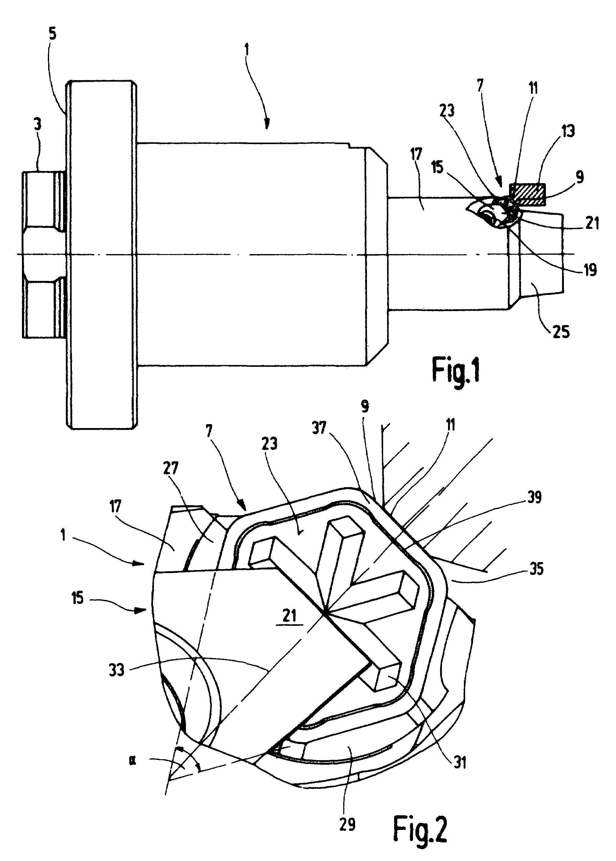
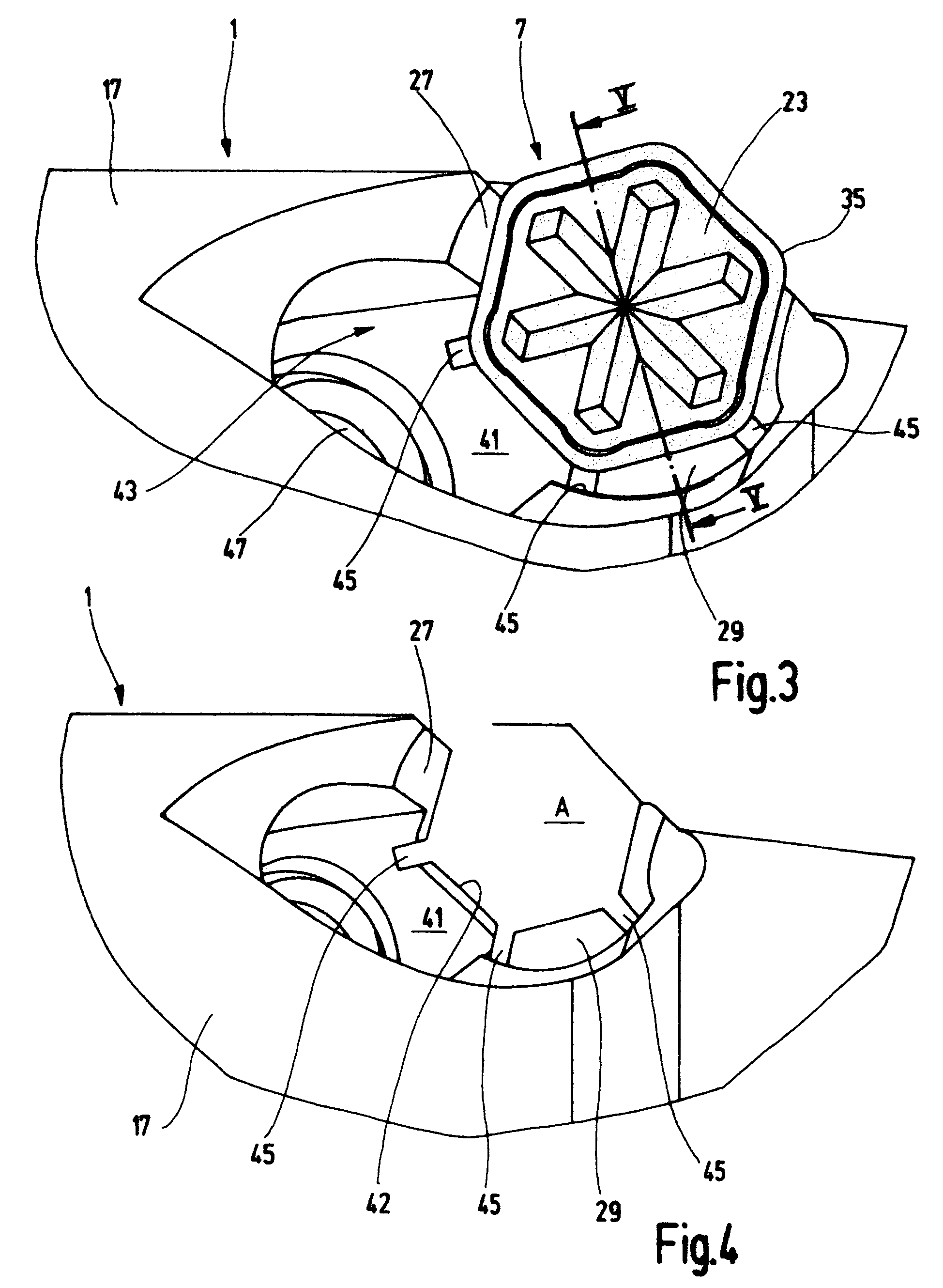
[0018]FIG. 1 shows a valve seat machining tool, i.e. a tool 1 which is used for machining valve seats in cylinder heads of internal combustion engines. On the left-hand side of the tool, there is a fastening stem 3 which is surrounded by an annular plane surface 5. The fastening stem 3 is used for coupling the tool 1 to a machine tool. The plane surface 5 ensures that the tool 1 is exactly aligned. The tool 1 may also be coupled to a machine tool in a different manner.

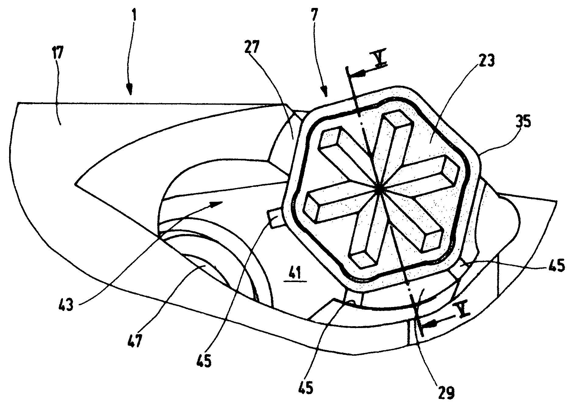
[0019]On the side of the tool 1 which lies opposite the fastening stem 3, there is a cutter tip 7 which has a geometrically defined cutting edge 9. The edge is used to remove chips from a valve seat 11 which is part of a valve seat ring 13 which is inserted into a cylinder head (not illustrated here) of an internal combustion engine.

[0020]The cutter tip 7 is fastened to the main body 17 of the tool 1 by a clamping claw 15. The clamping claw 15 is tightened with a clamping screw 19 in such a manner that a clamping lip 2...


PUM

PropertyMeasurementUnit
Angleaaaaaaaaaa
Shapeaaaaaaaaaa
Hardnessaaaaaaaaaa

Abstract

A tool for metal-cutting machining of a surface of an opening particularly of a valve seat in a cylinder head of an internal combustion engines. The tool has a cutter tip with at least one geometrically defined cutting edge. The cutter tip rests on two supporting regions in the tool which are arranged at an angle α, and an angle-bisecting line runs essentially perpendicularly with respect to the active cutting edge which then is removing chips from the valve seat. A claw holds the cutting tip to the tool end. Coolant and lubricant are supplied through an outlet from the claw.

Description

BACKGROUND OF THE INVENTION[0001]The invention relates to a tool for the metal-cutting machining of a surface, such as a valve seat in a cylinder head of an internal combustion engine and particularly to the configuration and attachment of the cutting tip thereof and relates to a method for the metal-cutting machining of such surface, such as a valve seat in a cylinder head of an internal combustion engines.[0002]Tools and methods of the type under discussion here are known. The tools have a cutter tip which comprises at least one geometrically defined cutting edge. With the aid of that edge, chips can be removed from the valve seat either by the tool being rotated with respect to a fixed workpiece or the workpiece being rotated with respect to a fixed tool. As a rule, the former of the two procedures is performed. The valve seat has a first annular surface which encloses, with reference to an imaginary central axis of the annular surface, a first angle of inclination of, for exampl...

Claims


Application Information

Patent Timeline
IPC IPC(8): B23B35/00B23B27/10B23C5/28B23B27/16B23B29/03B23C3/05
CPCB23B27/1625B23C3/055Y10T408/03B23B2200/086B23B2205/12B23B2226/125B23B2250/12Y10T408/5587Y10T407/14Y10T408/89Y10T409/303808Y10T407/2282Y10T407/1934Y10T408/865B23B2200/0404
Inventor KRESS, DIETERHABERLE, FRIEDRICH
Owner MAPAL FAB FUR PRAZIONSWERKZEUGE DR KRESS KG
Why Eureka
Try Eureka