
Electrical connector

a technology of electrical connectors and connectors, applied in the direction of electrical apparatus, connection, coupling device connection, etc., can solve the problems of long work time, high defective rate of products, complex assembly, etc., and achieve the effect of shortening work time and increasing yield ra

Inactive Publication Date: 2009-05-12
JESS-LINK PRODUCTS
View PDF18 Cites 21 Cited by
  • Summary
  • Abstract
  • Description
  • Claims
  • Application Information

AI Technical Summary

Benefits of technology

[0012]The object of the present invention is to provide an electrical connector which makes an insulating body, an inner flexible plug and a flexible cable be combined one another to shorten work time and increase yield rate.
[0014]The advantageous of the present invention are: the flexible cable and the electrical connecting terminals can be properly located and connected because of the inner flexible plug, thus, any weld processes aren't needed. Furthermore, because the flexible cable can be easily manufactured and the insulating body can be conveniently assembled, the work time is shortened and the yield rate is increased. The flexible cable can be closely combined by the force occurred between the inner flexible plug and the insulating body, thus, the problem of the asymmetric force and the cases of miss locating or inclining which make the circuitry badly contact and short circuit can be avoided.

Problems solved by technology

Thus, the assembly is complex as many components are needed in the electrical connector.2. After being removed the insulating sheath, the flexible cable needs to be combined with a strengthen board by adhesion to improve strength and stability, thereby keeping the flexible cable from dislocating under external force during the welding.3. It is difficult to weld the flexible cable and the terminals together, and the work time is long, thus, the defective rate of products is higher.
However, there still exist the questions such as the flexible cable cannot be properly located, and the asymmetric force occurs after fastening, which lead the flexible cable to be inserted onto a wrong location or incline to one side, thus, bad contact and short circuit may occur.

Method used


Image

  • Electrical connector
  • Electrical connector
  • Electrical connector

Examples


Embodiment Construction

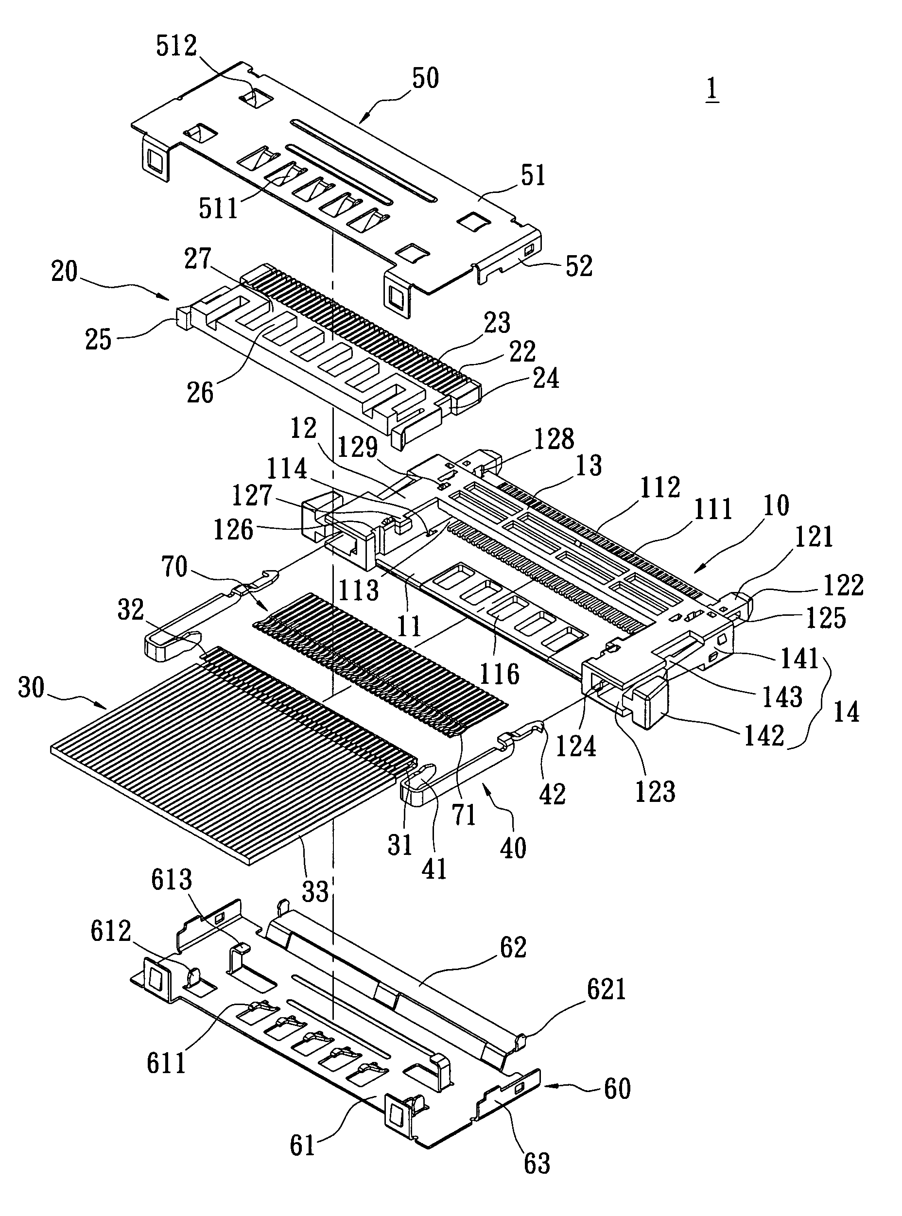
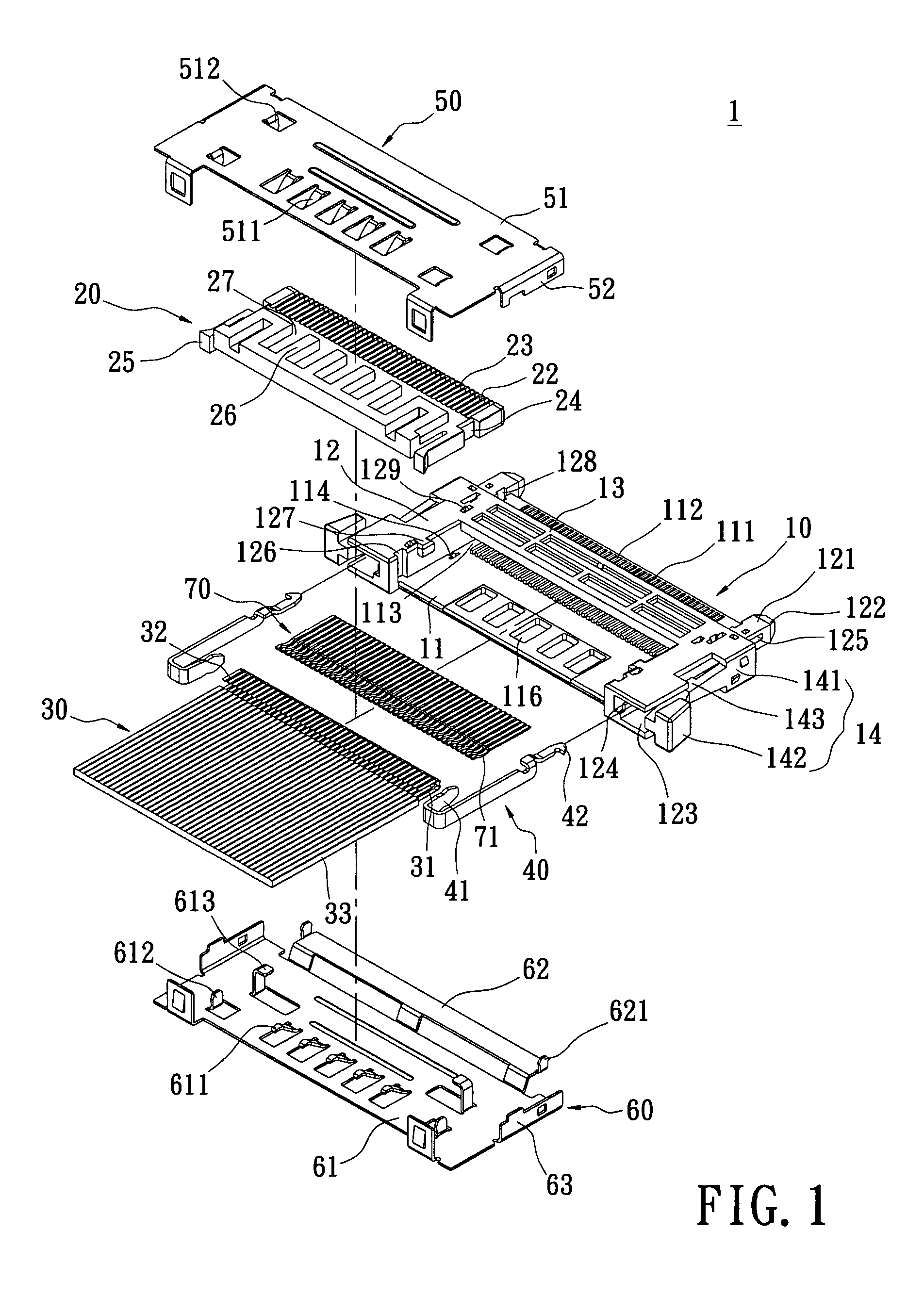
[0037]Please refer to FIG. 1, an electrical connector 1 of the present invention includes an insulating body 10, an inner flexible plug 20, a flexible cable 30, two hook portions 40, a first metal housing 50, a second metal housing 60, and a plurality of electrical connecting terminals 70.

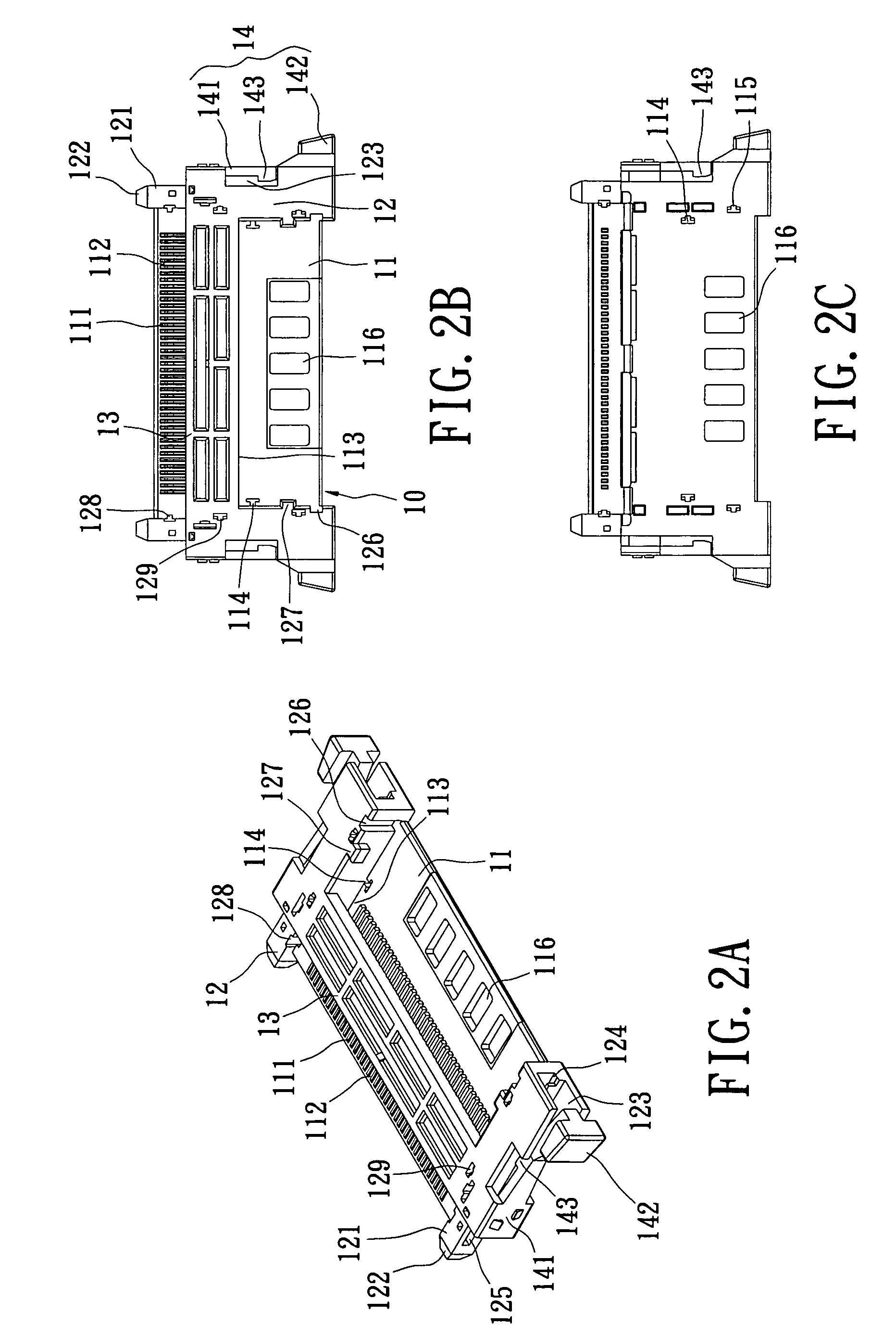
[0038]Please refer to FIGS. 2A-2C corporately, the insulating body 10 is made of insulating plastic and includes a base 11, two side portions 12, a top board 13, and two catching pieces 14. The two side portions 12 are respectively set on the left side and the right side of the base 11. The top board 13 stretches across the base 11 and is connected with the top board of the two side portions 12. A first receiving space 113 is form by the top side of the base 11, the inside walls of the two side portions 12 and the bottom of the top board 13, and the first receiving space 113 is used to receive the inner flexible plug 20 and the plurality of electrical connecting terminals 70.

[0039]A plurality of te...


PUM


Abstract

An electrical connector includes an insulating body, an inner flexible plug, two metal housings and a flexible cable. The insulating body includes a base, two side portions set on two opposite sides of said base respectively and a top board connected between the side portions. A plurality of terminal grooves is defined in the base. The inner flexible plug is combined in the insulating body. The metal housings cover the insulating body. The flexible cable is set between the insulating body and the inner flexible plug. The inner flexible plug defines a plurality of receiving slots corresponding to the terminal grooves. The receiving slots extend from top side of the inner flexible plug to its bottom side in a bent way thus the flexible cable can be electrically connected with electrical connecting terminals set in the terminal grooves. Therefore, the electrical connector is easily assembled and has a stable structure.

Description

BACKGROUND OF THE INVENTION[0001]1. Field of the Invention[0002]The present invention relates to an electrical connector, and more particular to an electrical connector which is combined with a flexible cable of which metal conducting wires are electrically connected with electrical connecting terminals of the electrical connector correspondingly.[0003]2. Description of Related Art[0004]Electrical connectors are combined in many electronic products to switch or relay signals or power supplies. Recently, flexible cables have been produced to meet the need of spatial allocation and circuit connection inside the electronic products. Flexible cables are also often combined with electrical connectors to yield optimal performance.[0005]A conventional electrical connector includes an insulating body, a plurality of terminals and a flexible cable. The plurality of terminals is inserted on the insulating body with an interval between every two adjacent terminals. The flexible cable is welded...

Claims


Application Information

Patent Timeline
Patent Type & Authority Patents(United States)
IPC IPC(8): H01R12/24
CPCH01R12/592H01R13/6275
Inventor LEE, WEN-LUNG
Owner JESS-LINK PRODUCTS
Learn More