Mobile air decontamination and purification unit

a technology of air decontamination and purification unit, which is applied in the direction of filtration separation, lighting and heating apparatus, crystallization separation, etc., can solve the problems of poor air quality, few existing air handling units address the needs of purification or decontamination, and relatively noisy

Inactive Publication Date: 2009-05-12
AIRINSPACE S E
View PDF40 Cites 37 Cited by
  • Summary
  • Abstract
  • Description
  • Claims
  • Application Information

AI Technical Summary

Benefits of technology

[0006]A fan support plate defines a boundary between the first and second chamber and a fan is mounted on the fan support plate. In a preferred embodiment, the fan is located substantially centrally relative to the side walls of the first and second chambers. The second chamber is also preferably balanced aerodynamically to help reduce the probability that air pressure differentials within the second chamber will induce noise generating imbalances within the fan. The walls of the second chamber also preferably include noise abatement materials, which further reduce the level of noise generated by the air treatment system. The size of the fan may be widely varied, but in many applications the fan is sized so that it is capable of conveying at least approximately 1000 cubic meters per hour of air through the air treatment system along the air flow path.
[0011]In still another aspect of the invention, an electronic control box is positioned at least partially within the second chamber and a matching structure is positioned within the second chamber that substantially mirrors an external geometry of the electronic control box to help aerodynamically balance the second chamber as seen by the fan.

Problems solved by technology

However, many buildings structures do not have central HVAC systems and often those with central HVAC systems include some level of filtering, but not much if any air purification or decontamination abilities.
Very few existing air handling units address these needs, although there are some that do.
By way of example, one problem that is frequently encountered in large airflow rate air handling devices is that they can be relatively noisy and there are continuing efforts to reduce the noise generated by such devices.

Method used


Image

  • Mobile air decontamination and purification unit
  • Mobile air decontamination and purification unit
  • Mobile air decontamination and purification unit

Examples


Embodiment Construction

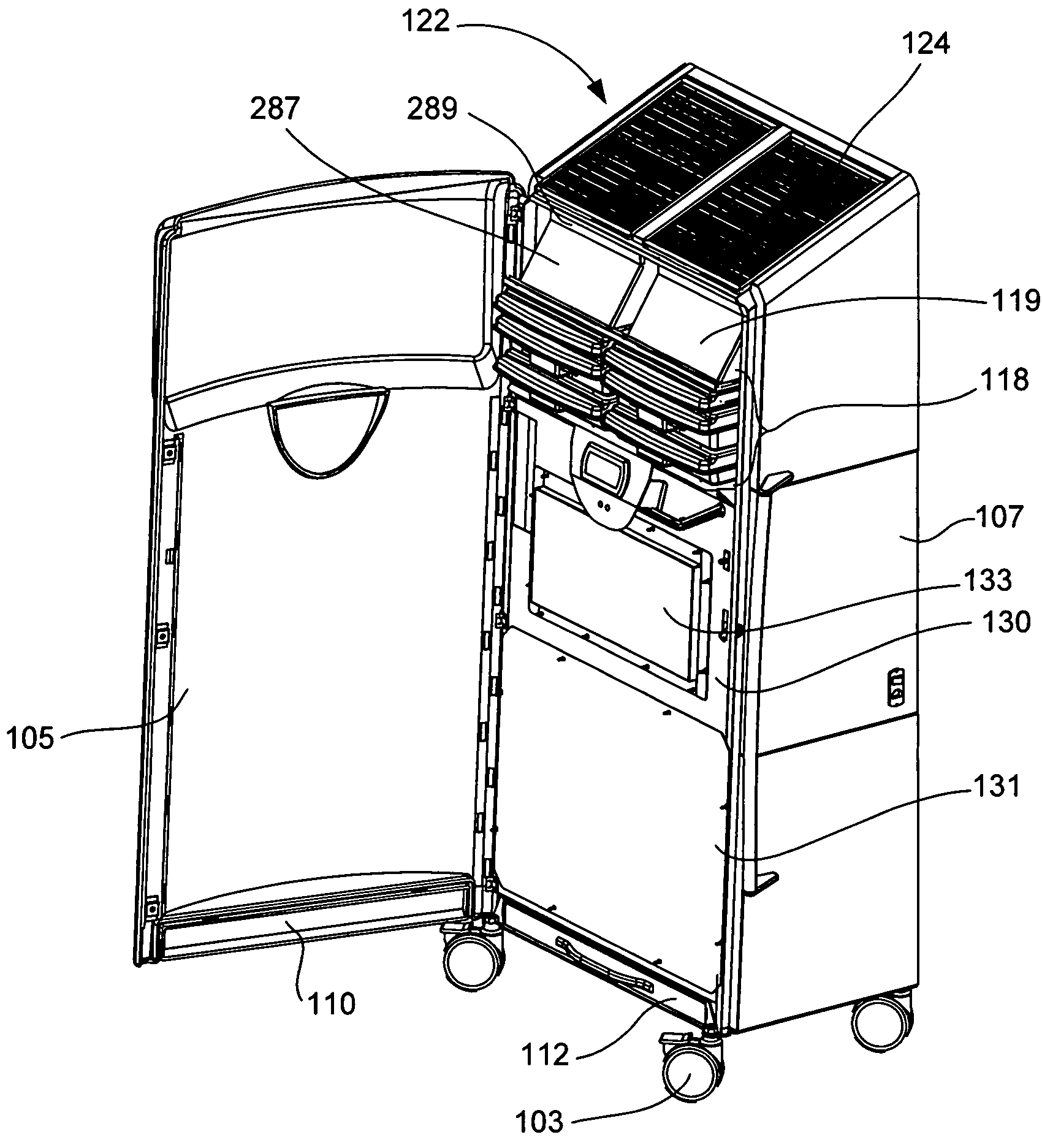
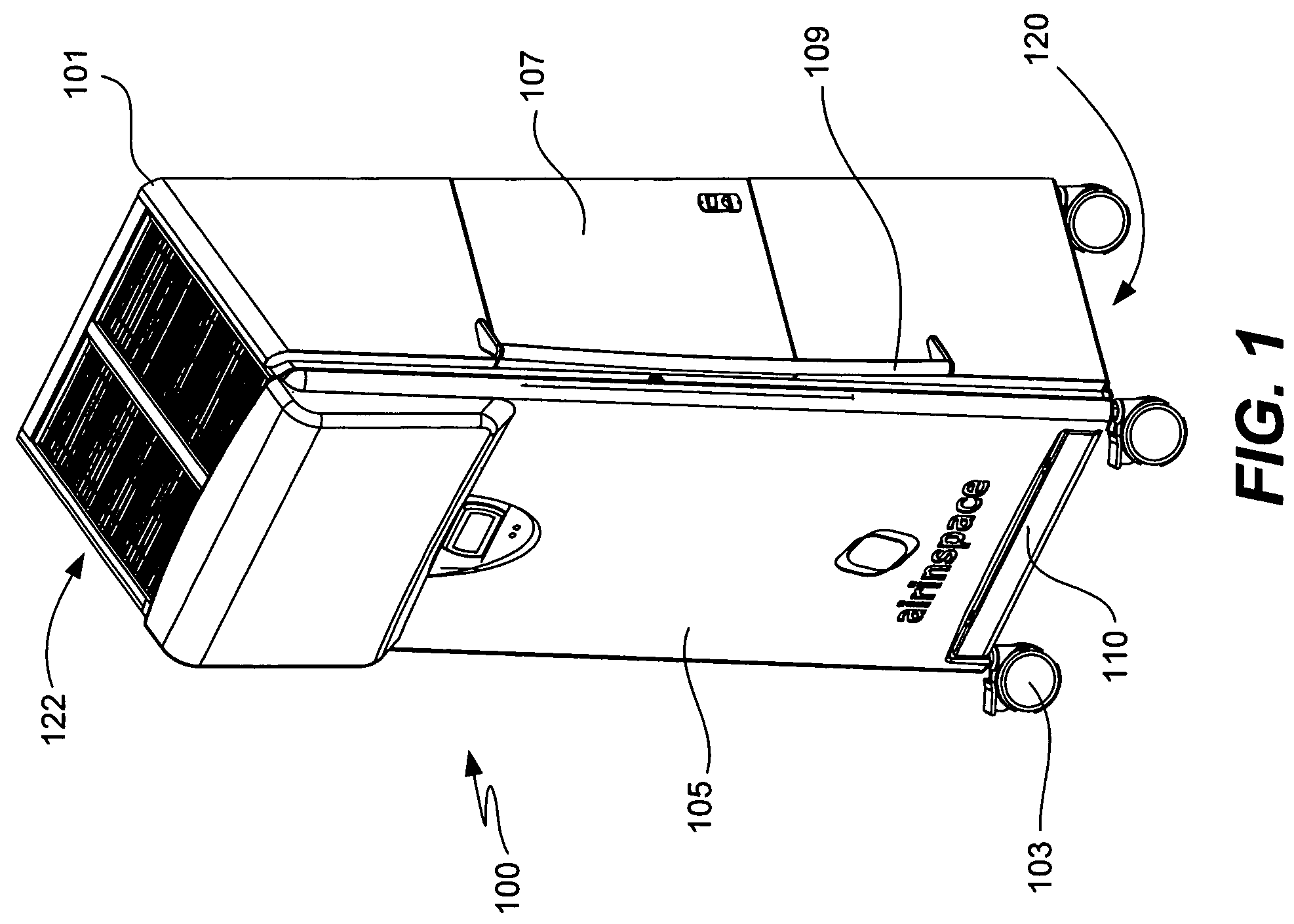
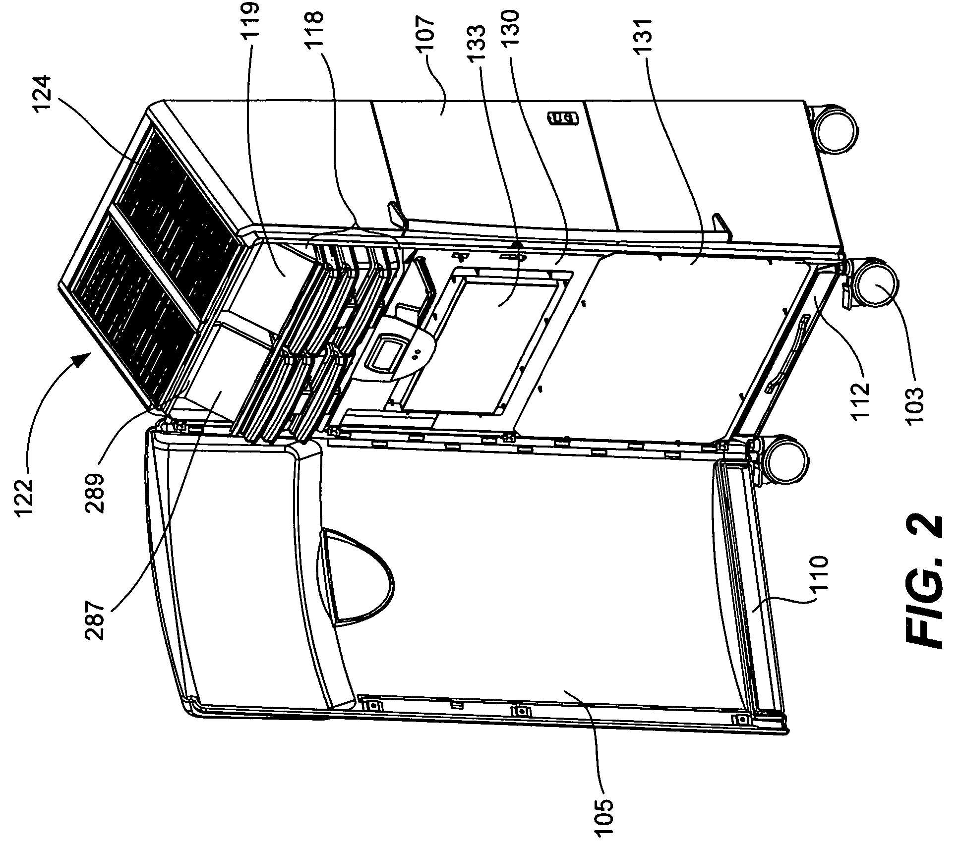
[0027]The present invention relates generally to transportable room air treatment systems, although some of the described components may be used in other air treatment systems as well. A transportable room air treatment system 100 in accordance with one embodiment of the present invention is illustrated in FIGS. 1-3. As seen therein, the air treatment system 100 has a cabinet or housing 101 that is mounted on rollers 103 so that the system may easily be transported and is generally portable. The cabinet 101 includes a frame 102 and has a front door 105 and a side compartment door 107. One or more grab bars 109 are provided on the sides of the cabinet 101 to facilitate transportation of the system. The front door 105 has a prefilter flap 110 that is pivotally mounted at a bottom end of the door. The prefilter flap 110 is arranged to provide ready access to a mechanical prefilter 112 located adjacent the system's air intake at the bottom end of the housing.

[0028]The bottom end of the ...


PUM

PropertyMeasurementUnit
distanceaaaaaaaaaa
heightaaaaaaaaaa
heightaaaaaaaaaa

Abstract

A variety of transportable air treatment system improvements are described. In one aspect of the invention, the system is designed to significantly reduce the noise generated during operation. In another aspect, an easily removable cooling unit is provided. In still another aspect, an air treatment unit (as for example a plasma reactor) is provided that is arranged to filter the air stream, inactivate biological organisms and / or reduce or eliminate volatile organic compounds (VOCs) that are carried in the air stream. The air treatment unit may take the form of a plurality of stacked trays. In yet another aspect of the invention, the air treatment system further includes a duct unit that directs air from the air treatment unit to the treated air outlet. The duct unit is operable to clamp the stacked trays to help seal the stacked trays.

Description

BACKGROUND OF THE INVENTION[0001]The present invention relates generally to mobile air decontamination and purification units.[0002]There are currently a wide range of technologies that are used to decontaminate, purify and / or filter air. Within building structures (e.g., commercial buildings, hospitals, residential dwellings, etc.) the purification and filtering systems are sometimes built into a central heating, air conditioning and ventilation (HVAC) system. However, many buildings structures do not have central HVAC systems and often those with central HVAC systems include some level of filtering, but not much if any air purification or decontamination abilities. Therefore, there are a wide variety of applications where it is desirable to provide an air filtering, purification and / or decontamination unit that is suitable for treating the air in a room.[0003]In some applications such as in infectious disease units of a hospital, it may be very desirable to provide room air treatm...

Claims


Application Information

Patent Timeline
Patent Type & Authority Patents(United States)
IPC IPC(8): A62B7/08F24F1/0076F24F1/035F24F1/0353
CPCB03C3/011B03C3/155B03C3/32F24F1/0007F24F3/166F24F7/007F24F2001/004F24F2001/0096F24F2003/1635F24F2003/1682F24F2221/12F24F1/0018F24F1/005F24F1/0071Y02A50/20F24F8/194F24F8/30F24F8/192F24F1/0076F24F1/035F24F1/0353
Inventor DESCOTES, LAURENTPERRIER, AYMERICDARRACQ, VIVIENBERGERON, VANCEFULLANA, LAURENT ADRIEN
Owner AIRINSPACE S E
Why Eureka
Try Eureka