Rotatable remote controlled porch light

a remote control and porch light technology, applied in the field of porch lights, can solve the problems of damage to the structure and/or the light, inability to make immediate changes in inability to change the direction of the light beam, etc., to achieve compact design of the light, rapid change of direction, and large degree of horizontal and vertical rotation of the lamp

Inactive Publication Date: 2009-05-12
WORSHAM DAVID +1
View PDF6 Cites 32 Cited by
  • Summary
  • Abstract
  • Description
  • Claims
  • Application Information

AI Technical Summary

Benefits of technology

[0005]The remote controlled light of the present invention has a circular base seat with a circular fixed seat having an internal ring gear attached to the base seat. Between the base seat and the fixed seat is a rotating connecting seat which rotates freely on the base seat and the fixed seat. A rotation driving seat fits within the base seat and connects to the rotating connecting seat so that the rotation driving seat can rotate freely within the base seat around its axis in a horizontal direction. A lamp holder is attached rotatably to the rotation driving seat so that the lamp holder can rotate about its axis of rotation in a vertical direction. The rotation driving seat has a first reversible rotation motor with a driving gear that engages the internal ring gear in the fixed seat so that the reversible rotation motor will turn the rotation driving seat horizontally to the left or to the right as the driving gear is turned by the first motor. The rotation driving seat has a second reversible rotation motor with a driving gear that engages a circular gear rack on the lamp holder to rotate the lamp holder vertically up and down as the driving gear is turned by the second motor. The rotation driving seat and the lamp holder have stopper pins to limit the degree of rotation of the light so that it will not damage, or be damaged by, the structure to which it is attached. In order to set the light on the structure so that it is centered within the arc of its horizontal rotation, the light has an adjusting board which attaches to a structure and which interfaces between the base seat and the structure to which the base seat is to be attached. Thus, the adjusting board is first attached to the structure and then the base seat is attached rotatably to the adjusting board. The base seat can then be rotated as desired to center the light within its arc of horizontal rotation, and then the base seat can be fastened to the adjusting board so as not to rotate. The rotation driving seat also has a receiver to receive RF signals remotely from a hand held transmitter to control the electric power to the lamp or the drive motors. The rotation driving seat can have other electronic devices for monitoring, surveillance, videoing, and for wireless transmission of signals to any desired communication network. An advantage of the porch light of the present invention is a light that can be controlled remotely to turn the lamp on and off and to rapidly change the direction of the light beam in both the horizontal and vertical directions.
[0006]Another advantage is the use of a rotating connecting seat between the base of the light and a rotating drive seat so that the rotating drive seat and lamp holder can rotate independently of the base, allowing for a compact design of the light while providing a large degree of horizontal and vertical rotation of the lamp.
[0007]Another advantage is a system of stopper pins that limit the degree of rotation of the lamp in the vertical and horizontal directions so that rotation of the lamp will not damage the lamp or the house or building to which it is attached.

Problems solved by technology

With existing porch lights or flood lights, however, it is impossible to make immediate changes in the direction of the light beam.
Conventional porch lights and flood lights popularly used today are unable to have the direction of the light beam varied or turned on and off by means of radio frequency (RF) remote control at any time whenever required by a user.
Although lights can be made to rotate, the degrees of rotation needs to be accurately controlled or the light may rotate into the structure to which it is attached and damage the structure and / or the light.

Method used


Image

  • Rotatable remote controlled porch light
  • Rotatable remote controlled porch light
  • Rotatable remote controlled porch light

Examples


Embodiment Construction

[0018]While the following description details the preferred embodiments of the present invention, it is to be understood that the invention is not limited in its application to the details of construction and arrangement of the parts illustrated in the accompanying drawings, since the invention is capable of other embodiments and of being practiced in various ways.

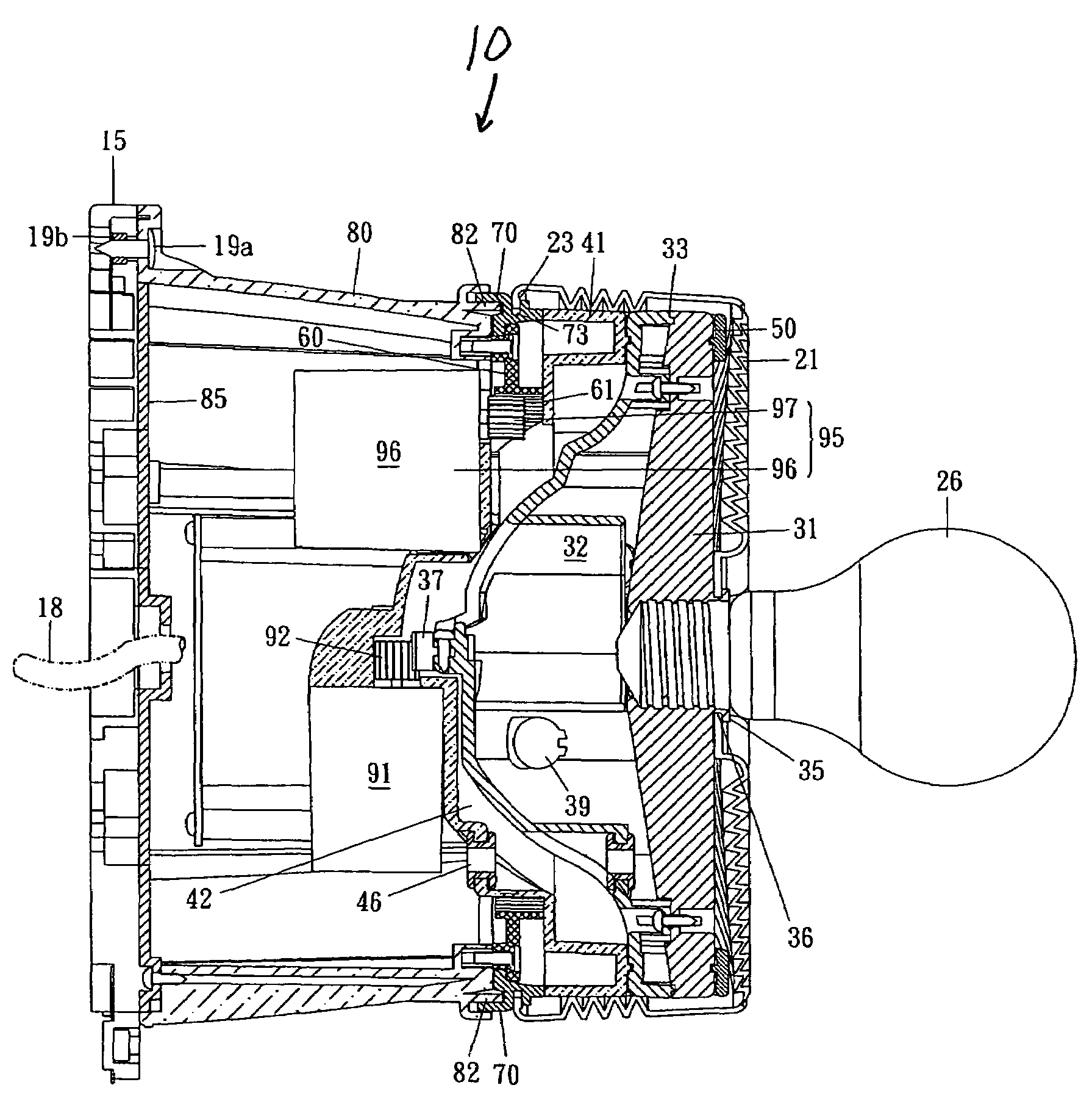
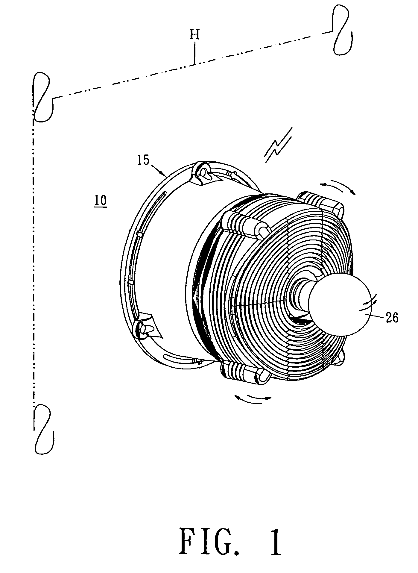
[0019]Referring to FIG. 1, a porch light 10 of the present invention can be installed on an outer wall or under the eaves of a home or building H, and can be turned on or off by means of a manually operated RF transmitter for illuminating an area around the home or building H. The direction of the light's beam may be changed and controlled also by means of a manually operated RF transmitter.

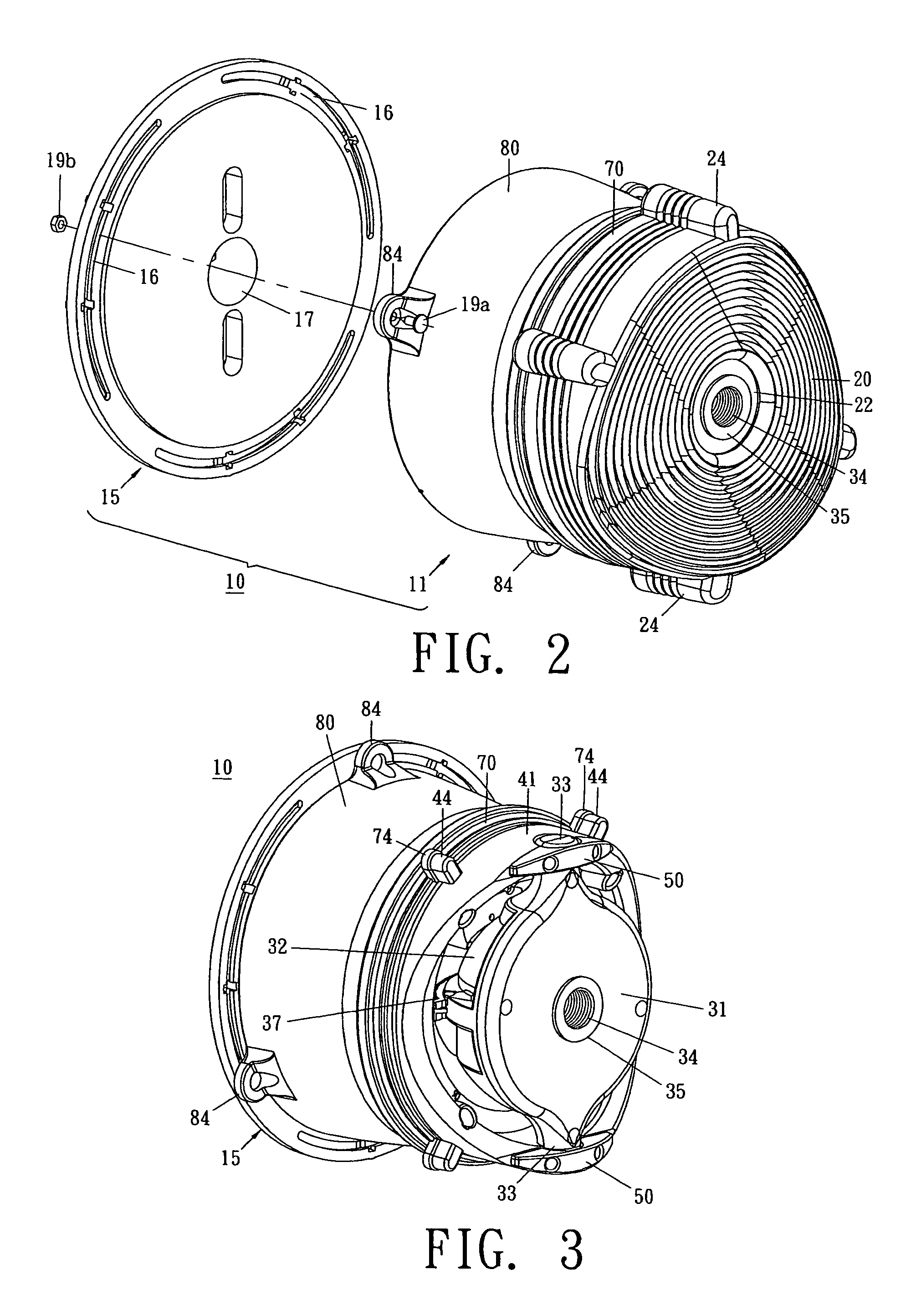
[0020]Referring to FIGS. 2-7, the porch light 10 has an adjusting board 15 which has plural ring-slots 16 and a penetrating hole 17 formed on its surface. The adjusting board 15 is securely fastened and installed on the outer wall or un...


PUM


Abstract

A remote controlled porch light that has a rotating seat on a base seat, and a rotation driving seat fitting within the base seat. The rotation driving seat has a first reversible motor to rotate the rotation driving seat and lamp to the left or right. A movable lamp holder is attached rotatably to the rotation driving seat. The rotation driving seat has a second reversible motor to rotate the movable lamp holder and lamp up or down. One or more stopper pins in the rotation driving seat limit the degree of horizontal rotation of the rotation driving seat. The base seat is adjustable on an adjusting board to position the light within the center of its arc of rotation, allowing the stopper pins to limit the degree of rotation of the light so that the rotation will not damage the lamp or the house or building to which the light is attached.

Description

BACKGROUND OF THE INVENTION[0001]1. Field of the Invention[0002]The present invention relates to porch lights, and, more particularly, to a wireless remote controlled porch light having a rotation driving seat to turn the light source horizontally and vertically, stop devices to limit the degree of horizontal and vertical rotation, and an adjusting board to center the light between the light's extremes of horizontal rotation.[0003]2. Technical Background[0004]Normally the porch light for a building or house is installed on the outer wall or under the eaves, and has a light beam aimed in a fixed direction to illuminate a fixed area. With existing porch lights or flood lights, however, it is impossible to make immediate changes in the direction of the light beam. Conventional porch lights and flood lights popularly used today are unable to have the direction of the light beam varied or turned on and off by means of radio frequency (RF) remote control at any time whenever required by a...

Claims


Application Information

Patent Timeline
Patent Type & Authority Patents(United States)
IPC IPC(8): H01K1/62
CPCF21S8/033F21V14/02F21V21/15F21V21/30F21V23/0442F21V31/005F21V27/00F21W2131/10F21W2131/107
Inventor WORSHAM, DAVIDMAO-SHEN, WANG
Owner WORSHAM DAVID
Why Eureka
Try Eureka