High-efficiency electromagnetic reversing pneumatic pump

An electromagnetic reversing and high-efficiency technology, which is applied in the direction of variable capacity pump components, pumps, piston pumps, etc., can solve the problems of lack of production technology and production conditions, high price, and large volume, and achieve convenient processing and maintenance. The effect of low cost and small size

Pending Publication Date: 2018-03-06
NINGBO UNIV
View PDF0 Cites 0 Cited by
  • Summary
  • Abstract
  • Description
  • Claims
  • Application Information

AI Technical Summary

Problems solved by technology

The core component of the pneumatic pump is the reversing mechanism. The current reversing mechanism mainly includes two types: mechanical type and valve type. The reversing mechanism has high requirements on the spool. The spool in our country is mainly made of alloy aluminum, which is fragile and not durable. However, the high-end spool in foreign countries is expensive, and our country does not have the production technology and production conditions.

Method used


Image

  • High-efficiency electromagnetic reversing pneumatic pump
  • High-efficiency electromagnetic reversing pneumatic pump
  • High-efficiency electromagnetic reversing pneumatic pump

Examples


Embodiment 1

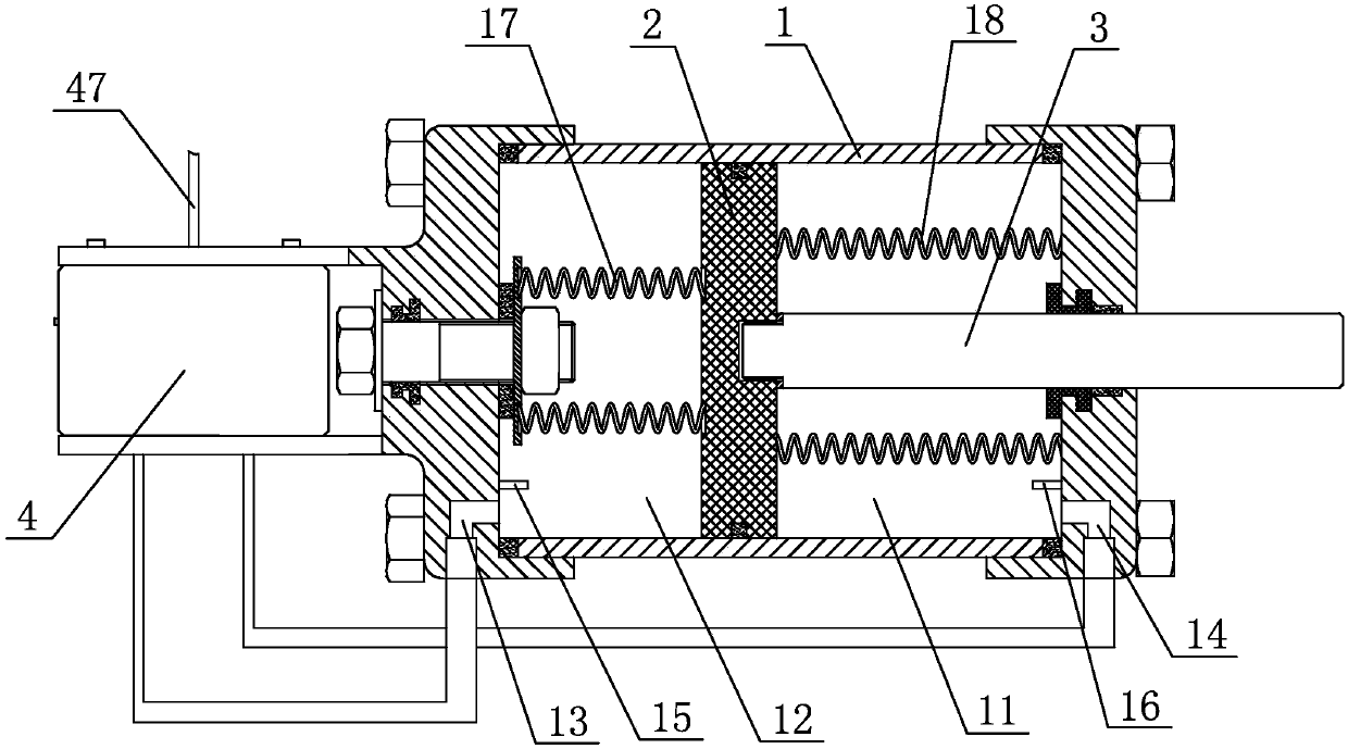
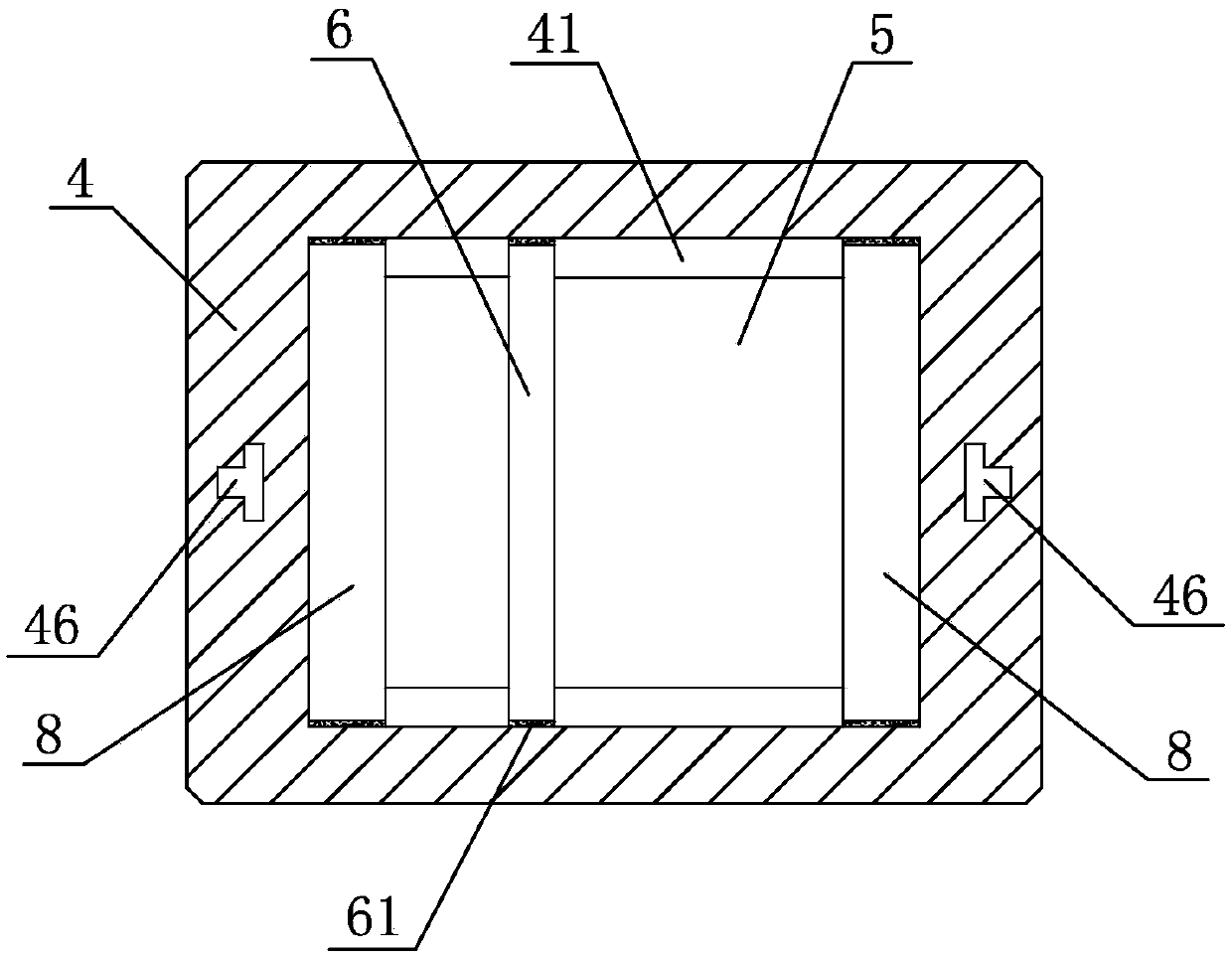
[0017] Embodiment 1: As shown in the figure, a high-efficiency electromagnetic reversing pneumatic pump includes a cylinder block 1, a piston 2 and a piston rod 3. The piston 2 is arranged in the cylinder block 1 and is sealed and slidably matched with the cylinder block 1. The piston 2 divides the inner cavity of the cylinder block 1 into a rod cavity 11 and a rodless cavity 12. The piston rod 3 is coaxially fixed with the piston 2 and passes out of the cylinder block 1 in the axial direction. The wall of the rodless cavity 12 is provided with a second A vent 13, a second vent 14 is arranged on the cavity wall of the rod cavity 11, an electromagnetic reversing mechanism is arranged between the first vent 13 and the second vent 14, and the electromagnetic reversing mechanism includes a casing 4 and The guide rail 5, the slide block 6 and the partition 7 arranged in the box body 4, the left and right ends of the guide rail 5 are respectively fixedly provided with strip electroma...

Embodiment 2

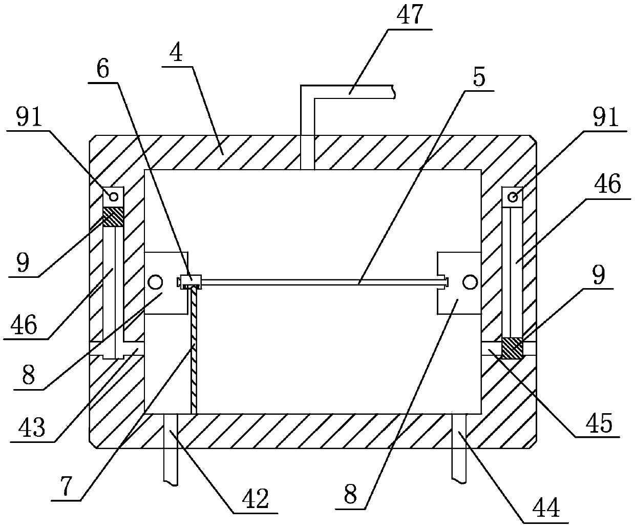
[0019] Embodiment 2: As shown in the figure, other structures are the same as Embodiment 1, and the difference is that the first exhaust hole 43 and the second exhaust hole 45 communicate with the upper part of the guide rail 5 in the box body 4 through the air pipe, A pressure sensor 10 is fixed inside the upper end of the box body 4 , and an air intake switch 48 is arranged on the first air pipe 47 .

[0020] In the above embodiment, the working process of the electromagnetic reversing pneumatic pump is as follows: through the first air pipe 47, the box body 4 is fed with air, and then the long electromagnet 8 located at the left end of the guide rail 5 is energized, and the electromagnet 91 located at the left side is energized. Power on, the strip electromagnet 8 absorbs the slider 6 and moves to the left end of the guide rail 5, while the block 9 on the left side is attracted by the electromagnet 91, and the first exhaust hole 43 is opened. At this time, the compressed gas...


PUM


Abstract

The invention discloses a high-efficiency electromagnetic reversing pneumatic pump, which comprises a cylinder body, a piston and a piston rod. cavity and rodless cavity, the piston rod and the piston are coaxially fixed and pass out of the cylinder body axially, the cavity wall of the rodless cavity is provided with a first ventilating port, and the cavity wall of the rod cavity is provided with a second ventilating port, features There is an electromagnetic reversing mechanism between the first vent and the second vent; the advantage is that the air exchange between the rod chamber and the rodless chamber in the cylinder body is realized by the electromagnetic reversing mechanism, so that the volume of the entire pneumatic pump is small , low noise, fast reversing action, high efficiency, and high precision; in addition, the electromagnetic reversing mechanism has a simple structure, convenient processing and maintenance, and relatively low cost.

Description

technical field [0001] The invention relates to a pneumatic pump, in particular to a high-efficiency electromagnetic reversing pneumatic pump. Background technique [0002] The pneumatic pump uses compressed gas as the power source, controls the flow direction of the compressed gas through the reversing mechanism, and the compressed gas drives the cylinder piston to move, and realizes the function of outputting reciprocating linear motion. The core component of the pneumatic pump is the reversing mechanism. The current reversing mechanism mainly includes two types: mechanical type and valve type. The reversing mechanism has high requirements on the spool. The spool in my country is mainly made of alloy aluminum, which is fragile and not durable. However, the high-end spool in foreign countries is expensive, and my country does not have the production technology and production conditions. Contents of the invention [0003] The technical problem to be solved by the present i...

Claims


Application Information

Patent Timeline
Patent Type & Authority Applications(China)
IPC IPC(8): F04B35/02F04B39/10F04B39/08
CPCF04B35/008F04B39/08F04B39/1046
Inventor 杨航城马志勇陈啸谷钱峰
Owner NINGBO UNIV
Why Eureka
Try Eureka