
Scannable virtual rail method and ring oscillator circuit for measuring variations in device characteristics

a virtual rail and measurement method technology, applied in pulse manipulation, pulse technique, instruments, etc., can solve the problems that ring oscillator test circuits typically do not provide information about random local variation of devices, nor of systematic variation

Inactive Publication Date: 2009-05-12
IBM CORP
View PDF3 Cites 21 Cited by
  • Summary
  • Abstract
  • Description
  • Claims
  • Application Information

AI Technical Summary

Benefits of technology

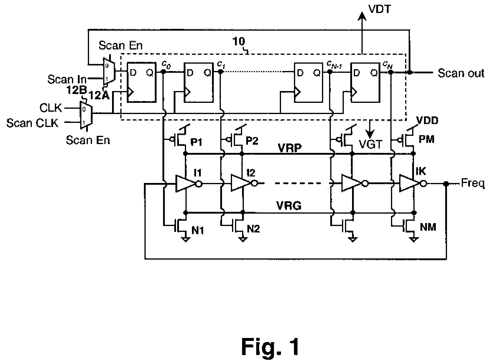
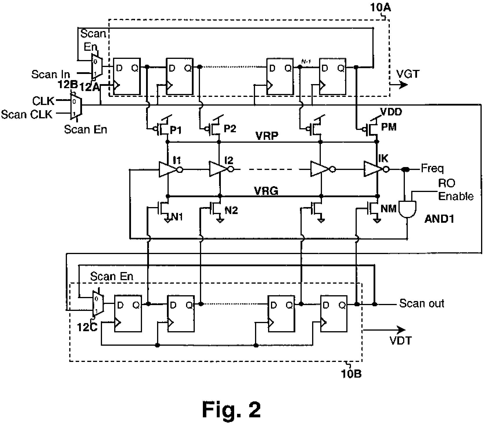
The invention is a method and circuit for measuring variations in device characteristics in a ring oscillator circuit. The circuit is operated from a virtual power supply rail that is connected to the actual power supply rail by a plurality of header transistors. The transistors are controlled by programmable elements, which allow for the measurement of variations in transistor performance by enabling each transistor in turn. The transistors can be enabled on different virtual power supply rails, making it possible to study the impact on the frequency of the ring oscillator with one transistor enabled on one virtual power supply rail and multiple transistors enabled on the other virtual power supply rail. The programmable elements can be connected to the gates of the transistors or provided individually for each transistor. The invention provides a more efficient and flexible way to measure variations in device characteristics in a ring oscillator circuit.

Problems solved by technology

However, ring oscillator test circuits typically do not provide information about random local variation of device characteristics, nor of the systematic and variational differences between the P-channel devices and N-channel devices.

Method used


Image

  • Scannable virtual rail method and ring oscillator circuit for measuring variations in device characteristics
  • Scannable virtual rail method and ring oscillator circuit for measuring variations in device characteristics
  • Scannable virtual rail method and ring oscillator circuit for measuring variations in device characteristics

Examples


Embodiment Construction

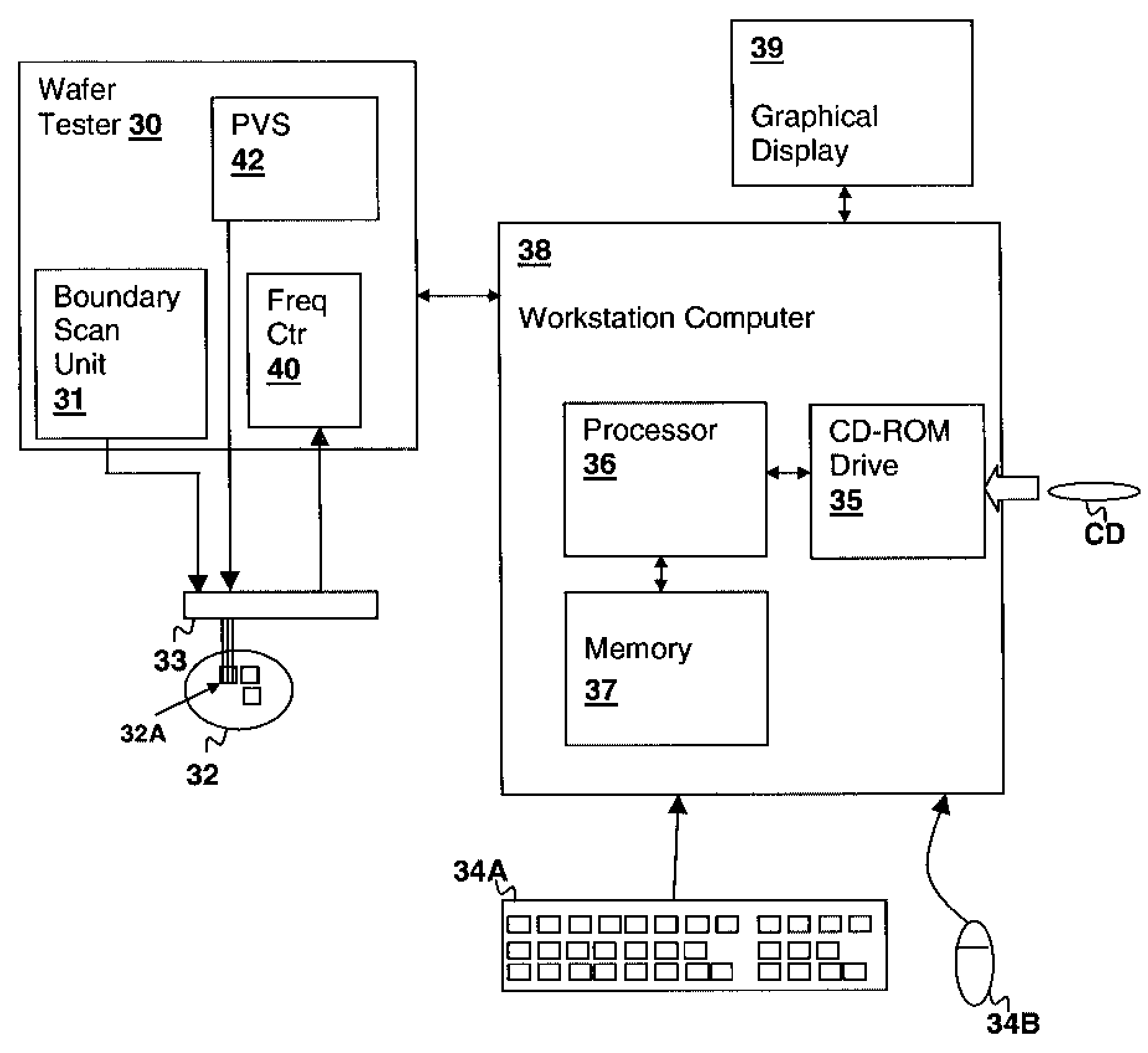
[0018]The present invention relates to a characterization circuit and method performed using a ring oscillator circuit in accordance with an embodiment of the present invention. The ring oscillator has at least one virtual power supply rail that is coupled to a power supply by a plurality of transistors that are physically distributed along the layout of the ring oscillator stages. By enabling each transistor in turn, while disabling the others, the variation of device characteristics, such as threshold voltage and / or channel resistance of the transistors can be observed from changes in the output frequency of the ring oscillator. The method may be a computer-controlled method partially embodied in a computer program having program instructions for carrying out the method by controlling a die / wafer tester to set the state of the virtual power supply rail transistors. Two virtual power supply rails, a higher voltage (e.g., VDD) and a lower voltage (e.g., ground) can be provided to th...


PUM


Abstract

A scannable virtual rail method and ring oscillator circuit for measuring variations in device characteristics provides the ability to study random device characteristic variation as well as systematic differences between N-channel and P-channel devices using a ring oscillator frequency measurement. The ring oscillator is operated from at least one virtual power supply rail that is connected to the actual power supply rail by a plurality of transistors controlled by a programmable source. The transistors are physically distributed along the physical distribution of the ring oscillator elements and each can be enabled in turn and the variation in ring oscillator frequency measured. The ring oscillator frequency measurements yield information about the variation between the transistors and N-channel vs. P-channel variation can be studied by employing positive and negative virtual power supply rails with corresponding P-channel and N-channel control transistors.

Description

BACKGROUND OF THE INVENTION[0001]1. Field of the Invention[0002]The present invention is related to integrated circuit characterization methods and circuits, and more particularly to a circuit and method for measuring variations in device characteristics in a test integrated circuit.[0003]2. Description of Related Art[0004]Characterization integrated circuits are in common use to evaluate designs on processes and have become increasingly necessary as processes have shrunk. Ring oscillator circuits are frequently used in such designs to study device characteristic variations that lead to variations in circuit parameters such as delay time. Performance screen ring oscillators (PSROs) are implemented along with functional circuits in a production integrated circuit to assist in production screening and as a design / process improvement tool. Since it is relatively easy to accurately measure the output frequency of a ring oscillator, and the output frequency is typically directly related ...

Claims


Application Information

Patent Timeline
Patent Type & Authority Patents(United States)
IPC IPC(8): H03F3/66G01R31/26
CPCG01R31/2884H03K3/0315G01R31/318577H03K2005/00058H03K2005/00234
Inventor AGARWAL, KANAK B.NASSIF, SANI R.
Owner IBM CORP
Learn More