Clock recovery from an optical signal with polarization impairments

a clock signal and impairment technology, applied in the field of optical communication networks, can solve the problems of inability to provide a reliable communication link, system extremely sensitive to polarization impairment, and vulnerable to severe chromatic dispersion and polarization impairmen

Active Publication Date: 2009-05-12
CIENA
View PDF25 Cites 41 Cited by
  • Summary
  • Abstract
  • Description
  • Claims
  • Application Information

AI Technical Summary

Benefits of technology

[0014]Accordingly, an object of the present invention is to provide methods enabling clock recovery from a highly distorted optical signal.

Problems solved by technology

However, this solution renders the system extremely sensitive to polarization impairments.
However, this solution diverts at least a portion of the energy of the received optical signal out of the data path, and is vulnerable to severe chromatic dispersion and polarization impairments at least in part due to inter-symbol interference (ISI).
This does not provide a reliable communication link.
The above noted problems, in respect of both systems, are compounded for polarization-division multiplexed signals, in which each transmitted polarization contains a respective different data signal.
Neither of the techniques suggested by Noé offers a robust solution for clock recovery from highly distorted optical signals of the type encountered in “real-world” optical communications networks.

Method used


Image

  • Clock recovery from an optical signal with polarization impairments
  • Clock recovery from an optical signal with polarization impairments
  • Clock recovery from an optical signal with polarization impairments

Examples


Embodiment Construction

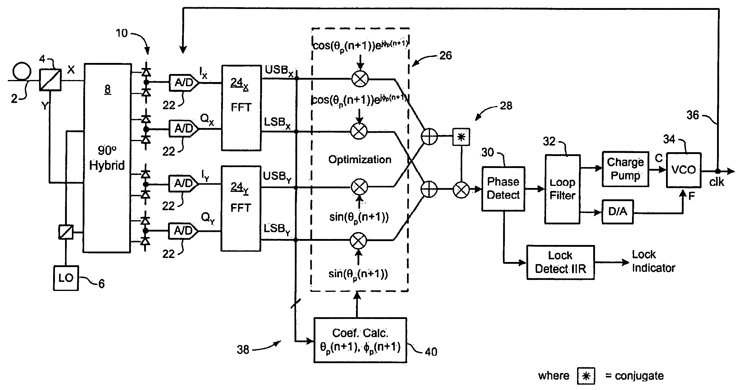
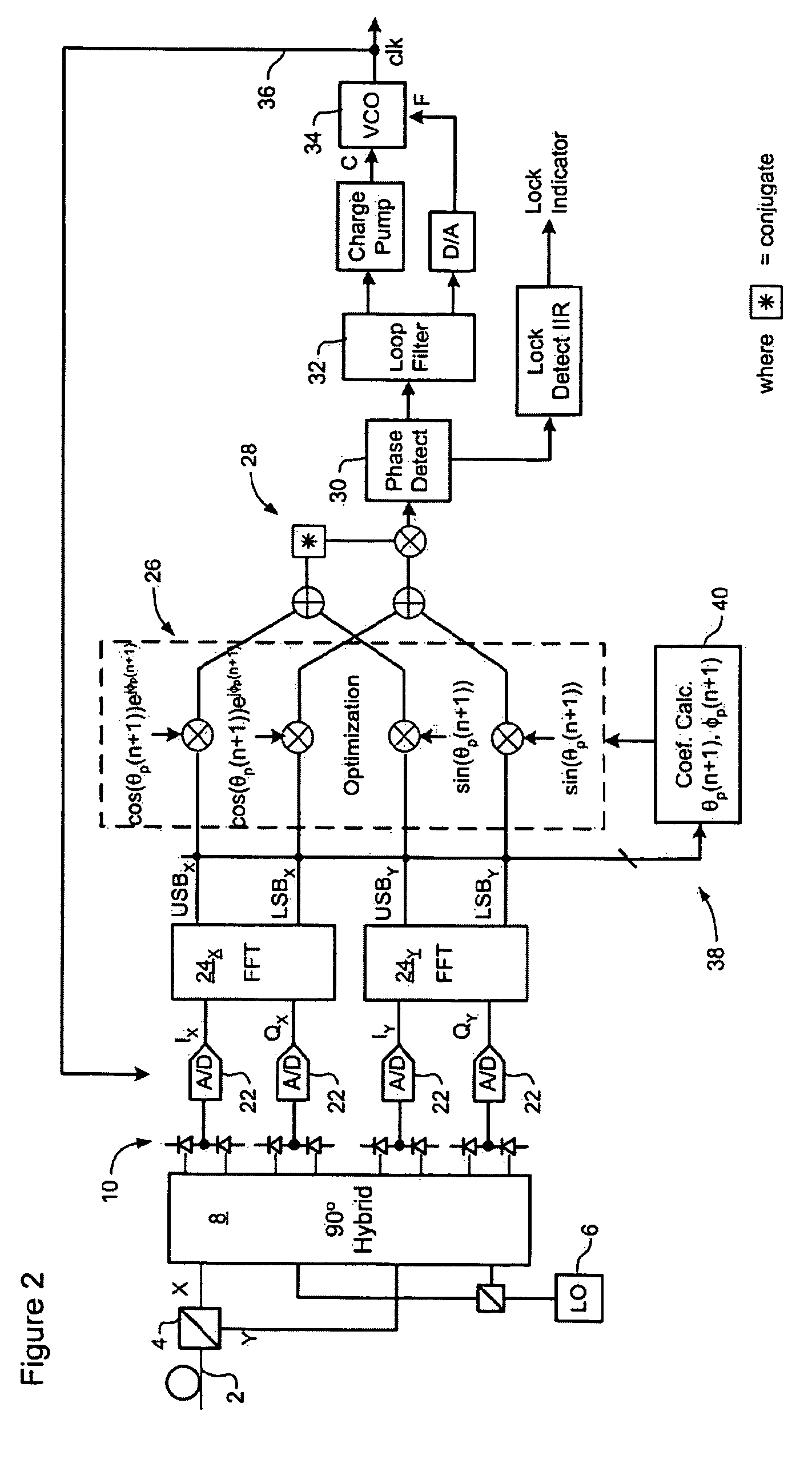
[0027]The present invention provides methods and systems enabling clock recovery from a highly distorted optical signal. Embodiments of the invention are described below, by way of example only, with reference to FIGS. 2-8.

[0028]In general, the present invention provides a clock recovery circuit in which a multi-bit sample stream of a received optical signal is digitally processed to compensate dispersion and / or polarization, an a clock signal recovered from the resulting compensated signal. It should be noted that in all cases the methods presented herein are “real-time”, in that the clock is recovered during reception of the optical signal, so that the recovered clock can be used to control the optical receiver, for example. This contrasts with typical laboratory bench-top systems, in which samples of an optical signal are stored for later processing, for example using an oscilloscope, to extract clock information.

[0029]Various methods may be used to recover a clock from a compens...


PUM


Abstract

A method of recovering a clock signal from an optical signal received through an optical communications system. A digital sample stream is processed to generate a dispersion compensated signal. The dispersion compensated signal is then tapped to obtain upper side band and lower side band signals of each received polarization of the optical signal. The upper side band sand lower side band signals are then processed to compensate polarization dependent impairments and the clock recovered from the resulting optimized.

Description

CROSS-REFERENCE TO RELATED APPLICATIONS[0001]This application claims benefit under 35 U.S.C. 119(e) from U.S. Provisional Patent Application Ser. No. 60 / 656,368 entitled: Optical Signal Transmitter System with Electronic Precompensation, which was filed on Feb. 28, 2005 and U.S. Provisional Patent Application Ser. No. 60 / 728,751, entitled: Automatic Gain Control, which was filed on Oct. 21, 2005.MICROFICHE APPENDIX[0002]Not Applicable.TECHNICAL FIELD[0003]The present invention relates to optical communications networks, and in particular to a method and apparatus for recovering a clock signal from optical signals received through an optical communications network.BACKGROUND OF THE INVENTION[0004]In the optical communications space, techniques used to detect data modulated onto an optical communications signal may be broadly group into two classes, namely “direct” detection and “coherent” detection. In “direct” detection techniques, the optical signal is made incident on a photodetec...

Claims


Application Information

Patent Timeline
Patent Type & Authority Patents(United States)
IPC IPC(8): H04B10/00
CPCH04L7/027H04J14/06H04L7/0029H03L7/085H03L2207/06H04B10/508H04L7/0083H04L7/0278
Inventor SUN, HANJOVANOVIC, SLOBODANWU, KUANG TSANBONTU, CHANDRAROBERTS, KIM BXU, JIANZHONG
Owner CIENA
Why Eureka
Try Eureka