Vehicle driving force control apparatus

a technology of driving force and control apparatus, which is applied in the direction of gearing, instruments, tractors, etc., can solve the problems of generator power, generator cannot flow, electric motor cannot generate drive torque, etc., and achieve the effects of preventing acceleration slippage, preventing acceleration slippage, and low friction coefficien

Active Publication Date: 2009-05-12
NISSAN MOTOR CO LTD
View PDF28 Cites 25 Cited by
  • Summary
  • Abstract
  • Description
  • Claims
  • Application Information

AI Technical Summary

Benefits of technology

[0008]In contrast, vehicles equipped with a traction control apparatus to prevent acceleration slippage of the drive wheels are controlled to prevent acceleration slippage when acceleration slippage in the drive wheels occurs such as when travelling on road surfaces with a low frictional coefficient by changing the upshift schedule. The upshift schedule changes the upshift variable speed line that upshifts from the 1 st speed gear position to the 2nd speed gear position of the automatic transmission to a high vehicle speed compared with a normal variable speed line and then reducing the engine rotational speed or providing a braking force to the drive wheels using the throttle opening degree or cutting fuel while controlling the upshift of the automatic transmission.
[0009]In this manner, if the shift schedule is changed by the traction control apparatus so as to control upshifts while acceleration slippage occurs and the acceleration slippage cancelled, the shift schedule will return to a shift schedule that uses the original normal variable speed line. Because of this, the engine rotational speed changes to a comparatively high state and the amount of power generated by the generator can overcome the counterelectromotive force of the electric motor allowing the generated current to be supplied to the electric motor by means of controlling the upshifting of the automatic transmission from the 1 st speed gear position to the 2nd speed gear position even if the vehicle speed exceeds the normal variable speed line while acceleration slippage occurs when driving the electric motor using the amount of power generated by the generator in vehicles equipped with a traction control apparatus. Because the shift schedule returns to a shift schedule that uses the original normal variable speed line when the acceleration slippage is cancelled in a state in which the electric motor is being driven, there is an unsolved problem of the danger of the automatic transmission shifting up to the 2nd speed gear position and the engine rotational speed decreasing thereby resulting in insufficient power generation or the impossibility of power generation.
[0010]Thereupon, an object of the present invention is to solve of the above-mentioned problems and provide a vehicle driving force control apparatus that can prevent the occurrence of insufficient power generation or the impossibility of power generation by the generator.

Problems solved by technology

It has been discovered that in the above mentioned driving force control apparatus that since the electric motor is driven by the electromotive force generated by the generator that is driven by the internal combustion engine, if the generator cannot overcome the counterelectromotive force of the electric motor, it cannot generator power.
Consequently, power generation current generated by the generator cannot flow and the electric motor cannot generate drive torque.
Because the shift schedule returns to a shift schedule that uses the original normal variable speed line when the acceleration slippage is cancelled in a state in which the electric motor is being driven, there is an unsolved problem of the danger of the automatic transmission shifting up to the 2nd speed gear position and the engine rotational speed decreasing thereby resulting in insufficient power generation or the impossibility of power generation.

Method used


Image

  • Vehicle driving force control apparatus
  • Vehicle driving force control apparatus
  • Vehicle driving force control apparatus

Examples


Embodiment Construction

[0026]Selected embodiments of the present invention will now be explained with reference to the drawings. It will be apparent to those skilled in the art from this disclosure that the following descriptions of the embodiments of the present invention are provided for illustration only and not for the purpose of limiting the invention as defined by the appended claims and their equivalents.

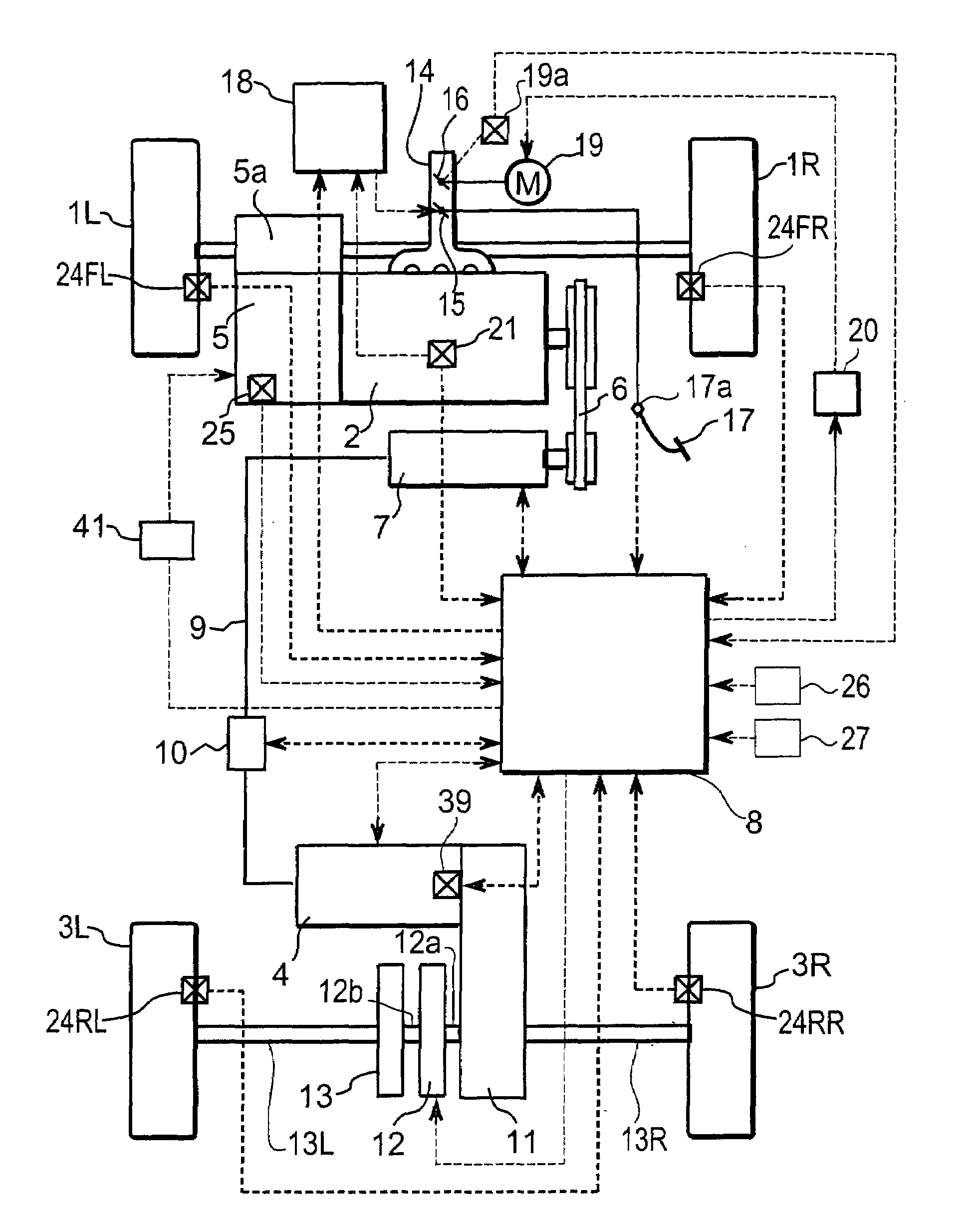
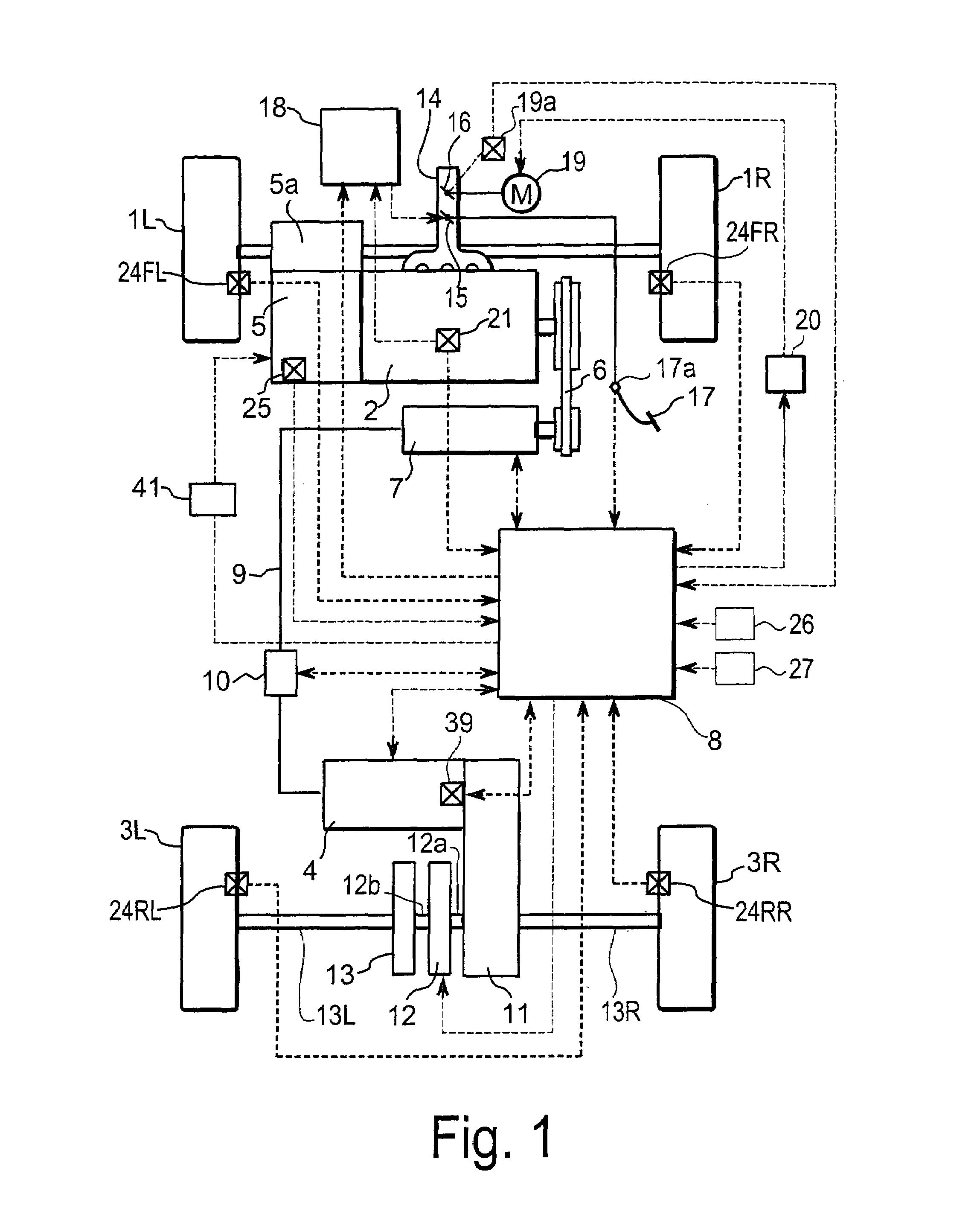
[0027]Referring initially to FIGS. 1 and 2, a vehicle driving force control apparatus will now be explained in accordance with a first embodiment of the present invention. As seen in FIG. 1, a four wheel drive vehicle is diagrammatically illustrated that is equipped with the vehicle driving force control apparatus in accordance with the present invention. As shown in FIG. 1, the vehicle in accordance with this embodiment has left and right front wheels 1L and 1R that are driven by an internal combustion engine or main drive source 2, and left and right rear wheels 3L and 3R that are driven by an el...


PUM


Abstract

A vehicle driving force control apparatus is provided to prohibit a change in a shift schedule that will cause insufficient power generation of a generator that supplies power to an electric motor to drive a first drive wheel. The vehicle driving force control apparatus has a shift schedule change section, a power sufficiency determining section and a shift schedule change prohibit section. The shift schedule change section is configured to change a shift schedule of a transmission of the main drive source. The power sufficiency determining section is configured to determine whether generated power of the generator will be insufficient by a change in the shift schedule by the shift schedule change section, when an electromotive force of the generator is driving the electric motor that supplies torque to the first drive wheel. The shift schedule change prohibit section is configured to prohibit a change of the shift schedule by the shift schedule change section, upon the power sufficiency determining section determining that the generated power of the generator will be insufficient.

Description

BACKGROUND OF THE INVENTION[0001]1. Field of the Invention[0002]The present invention relates to a vehicle driving force control apparatus configured so as to drive an electric motor that transmits drive torque to subordinate wheels by means of electromotive force generated by a generator.[0003]2. Background Information[0004]This type of vehicle driving force control apparatus has been proposed for both front and rear wheel drive vehicles (refer to Japanese Patent Utility Model No. 55-138129 (1st page, FIG. 2)) in which one pair of wheels from among the front wheels and rear wheels are driven by the power of an internal combustion engine through a transmission as the main drive wheels, and the other pair of wheels, from among the front wheels and rear wheels, is driven by an electric motor. The driving force of the internal combustion engine drives a generator and the electromotive force generated by this generator is supplied to an electric motor. Thereafter, when the accelerator p...

Claims


Application Information

Patent Timeline
Patent Type & Authority Patents(United States)
IPC IPC(8): G06F19/00F16H61/08B60W20/00B60K6/20B60K6/44B60K6/52B60K6/54B60K17/356B60K28/16B60L15/20B60L50/10B60L50/16B60W10/08B60W10/10F02D29/02F16H61/02F16H61/16F16H63/50
CPCB60K6/44B60K28/165B60L3/10B60L7/14B60L15/20B60W10/08B60W10/10F16H61/16B60K6/52Y02T10/7275B60L2240/423B60L2260/28B60W20/00B60W2510/085B60W2710/083F16H61/0213F16H2300/14Y02T10/623Y02T10/6265Y02T10/645Y10S477/901Y10T477/65Y02T10/62Y02T10/64Y02T10/72B60W2520/28B60W2510/083B60W2510/081
Inventor KADOTA, KEIJI
Owner NISSAN MOTOR CO LTD
Why Eureka
Try Eureka