
Method for a more efficient use of a combustion engine in a vehicle

a combustion engine and vehicle technology, applied in the direction of electric control, speed sensing governors, instruments, etc., can solve the problems of relatively high engine rotational speed, low engine efficiency, and inability to upshift to a new gear, so as to reduce unnecessary driving, save fuel, and reduce the effect of inefficient engine rotational speed

Active Publication Date: 2010-10-14
VOLVO LASTVAGNAR AB
View PDF36 Cites 7 Cited by
  • Summary
  • Abstract
  • Description
  • Claims
  • Application Information

AI Technical Summary

Benefits of technology

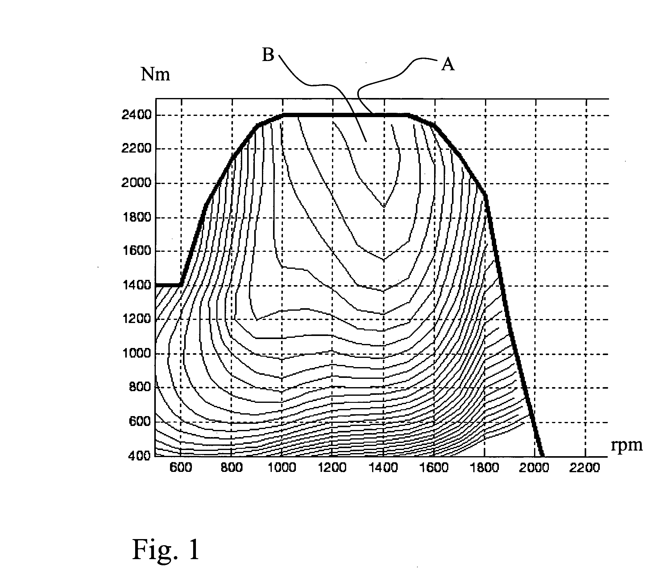
[0003]In vehicles equipped with an automatic transmission a situation can sometimes occur in uphill drive where a transmission control unit estimates that an upshift to a new gear will not be possible due to that the engine of the vehicle will not be able to accelerate the vehicle to a sufficiently high vehicle speed so that the engine will manage to drive the vehicle with said new gear engaged. An alternative to the estimation, that the engine of the vehicle will not be able to accelerate the vehicle to a sufficiently high vehicle speed, is to simply register that the engine rotational speed increase has stopped before reaching the right engine rotational speed for upshift. This usually leads to the engine being stuck or “hanging” at relatively high engine rotational speeds without the transmission being able to perform an upshift. A typical example for a heavy duty truck could be that the engine must increase its speed to above 1850 rpm to be able to after an upshift land on a rotational speed with the new gear engaged that gives the engine the possibility to produce enough torque to at least be able to maintain current vehicle speed. In order to gain a better margin it could be necessary to increase the engine rotational speed to even higher rotational speeds, such as 1900 to 1950 rpm, before a gear upshift to the new gear is initiated. At these relatively high engine rotational speeds the efficiency of the engine is relatively low, and having the engine stuck at these relatively high engine rotational speeds contributes to an increased fuel consumption.
[0016]According to a further embodiment of the method according to an aspect of the invention, said automatic controlling of the engine torque is independent of if a driver of the vehicle demands maximum engine output torque or not. Thus, a full automation will minimize the time the engine spends in the inefficient rotational speed area.

Problems solved by technology

In vehicles equipped with an automatic transmission a situation can sometimes occur in uphill drive where a transmission control unit estimates that an upshift to a new gear will not be possible due to that the engine of the vehicle will not be able to accelerate the vehicle to a sufficiently high vehicle speed so that the engine will manage to drive the vehicle with said new gear engaged.
This usually leads to the engine being stuck or “hanging” at relatively high engine rotational speeds without the transmission being able to perform an upshift.
At these relatively high engine rotational speeds the efficiency of the engine is relatively low, and having the engine stuck at these relatively high engine rotational speeds contributes to an increased fuel consumption.

Method used

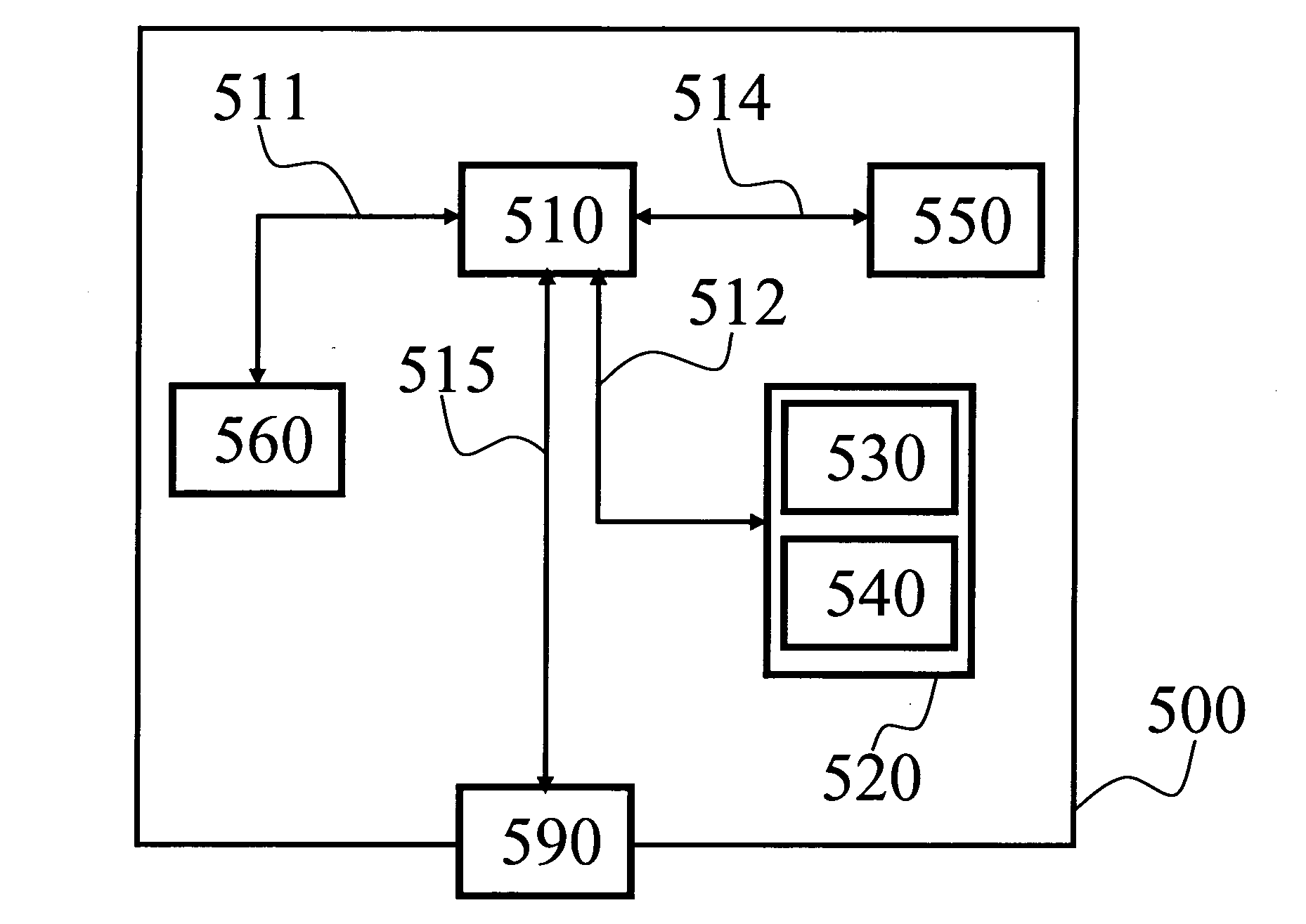
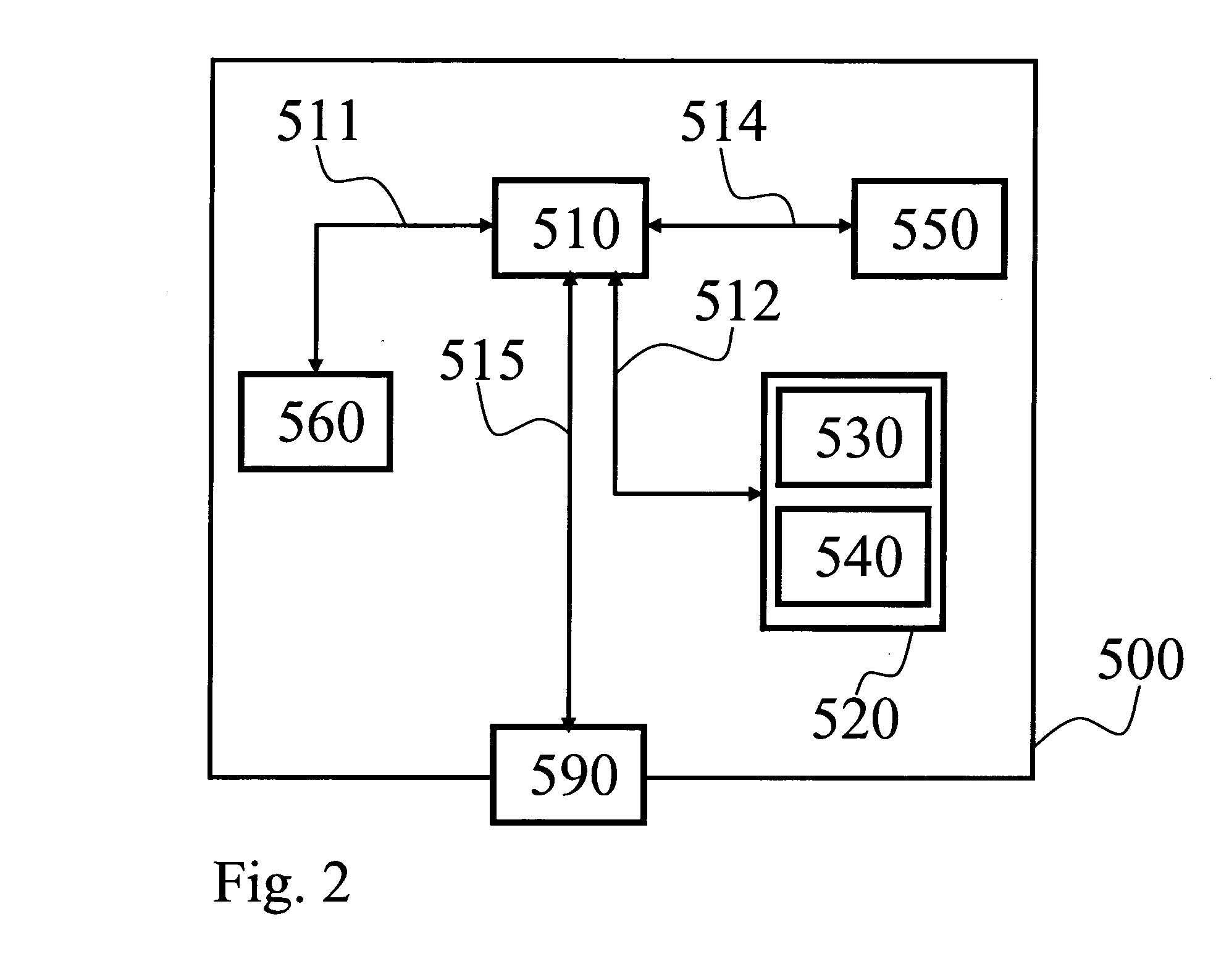

Image

  • Method for a more efficient use of a combustion engine in a vehicle
  • Method for a more efficient use of a combustion engine in a vehicle
  • Method for a more efficient use of a combustion engine in a vehicle

Examples


Embodiment Construction

[0020]In one embodiment the vehicle is equipped with an internal combustion engine, an automatic step geared transmission and driven wheels, to which drive power from the engine can be transmitted via different gears in the transmission. The different gears are selected and engaged by a transmission control unit. Each selectable gear has a predetermined gear ratio.

[0021]Gear selections and shift decisions are made by said control unit based on certain measured and / or calculated parameters such as vehicle speed, engine speed, rate of change of vehicle speed, rate of change of engine speed, throttle control position, rate of change of throttle control position, actuation of a vehicle braking system, currently engaged gear ratio and the like are known from prior art.

[0022]In a first preferred embodiment of the invention said control unit is programmed to estimate if a selected, not yet performed upshift is feasible. This estimation is based on a calculation with input parameters such a...


PUM


Abstract

A method for a more efficient use of a vehicle combustion engine during driving, the vehicle including an automatic step geared transmission. The method includes the steps of sensing current engine rotational speed and engine rotational speed increase, estimating necessary minimum upshift engine rotational speed for a coming gear upshift, registering that the engine rotational speed stops increasing without reaching the minimum upshift engine rotational speed, and where the engine rotational speed stops increasing relatively close to a maximum engine rotational speed where engine efficiency is relatively low and, automatically controlling engine output torque in order to limit the engine rotational speed to a first predetermined engine speed where engine efficiency is relatively high.

Description

BACKGROUND AND SUMMARY[0001]The present invention relates to a method for a more efficient use of a combustion engine in a vehicle, by, during certain vehicle conditions, automatically controlling engine rotational speed in a predetermined way.[0002]The present invention also relates to a computer program and computer program product both to be used with a computer for executing said method.[0003]In vehicles equipped with an automatic transmission a situation can sometimes occur in uphill drive where a transmission control unit estimates that an upshift to a new gear will not be possible due to that the engine of the vehicle will not be able to accelerate the vehicle to a sufficiently high vehicle speed so that the engine will manage to drive the vehicle with said new gear engaged. An alternative to the estimation, that the engine of the vehicle will not be able to accelerate the vehicle to a sufficiently high vehicle speed, is to simply register that the engine rotational speed inc...

Claims


Application Information

Patent Timeline
Patent Type & Authority Applications(United States)
IPC IPC(8): G06F19/00B60W10/10B60W30/18B60W50/08
CPCB60W10/06B60W30/1882B60W50/087F02D29/02F02D31/001F16H2061/161F02D2250/18F02D2200/701F16H2059/363F16H2059/366F02D41/0215B60W50/0097
Inventor ERIKSSON, ANDERSTEMPLIN, PETER
Owner VOLVO LASTVAGNAR AB
Learn More