Connector for connecting building components

a technology for connecting building components and connecting rods, applied in the direction of rod connections, curtain suspension devices, machine supports, etc., can solve the problems of insufficient strength of conventional connector designs, inability to efficiently and effectively resist uplift, and l-shaped connectors that may not necessarily handle the variety of loads

Active Publication Date: 2009-05-19
THE STEEL NETWORK
View PDF34 Cites 53 Cited by
  • Summary
  • Abstract
  • Description
  • Claims
  • Application Information

AI Technical Summary

Benefits of technology

[0006]In another embodiment of the connector of the present invention, the connector is provided with an upturned flange that extends along one side of the base plate opposite the juncture. Further, in another embodiment, the connector is provided with a reinforcing member or block that extends over the base plate. In one particular design, the reinforcing member is tightly secured adjacent the base plate so as to reinforce the base plate and impart sufficient strength to generally prohibit the base plate from bending or being deformed in the case of certain loads being applied to the connector.

Problems solved by technology

However, typical L-shaped connectors may not necessarily handle the variety of loads and forces that are sometimes experienced where studs are joined or secured to a floor or other support structure.
More particularly, conventional connector designs may not always efficiently and effectively resist uplift, horizontal and rotational loads that are experienced about connecting points between such studs and an adjacent support structure.

Method used


Image

  • Connector for connecting building components
  • Connector for connecting building components
  • Connector for connecting building components

Examples


Embodiment Construction

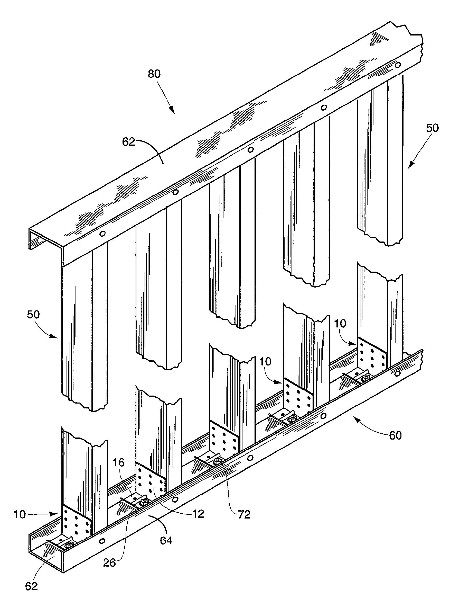
[0018]With further reference to the drawings, the connector of the present invention is shown therein and indicated generally by the numeral 10. As will be appreciated from subsequent portions of the disclosure, connector 10 is adapted to be used in a building construction assembly and while the connector 10 may be utilized in different ways, in one exemplary embodiment the connector 10 is utilized to fasten or connect metal building studs to an underlying or overlying support structure.

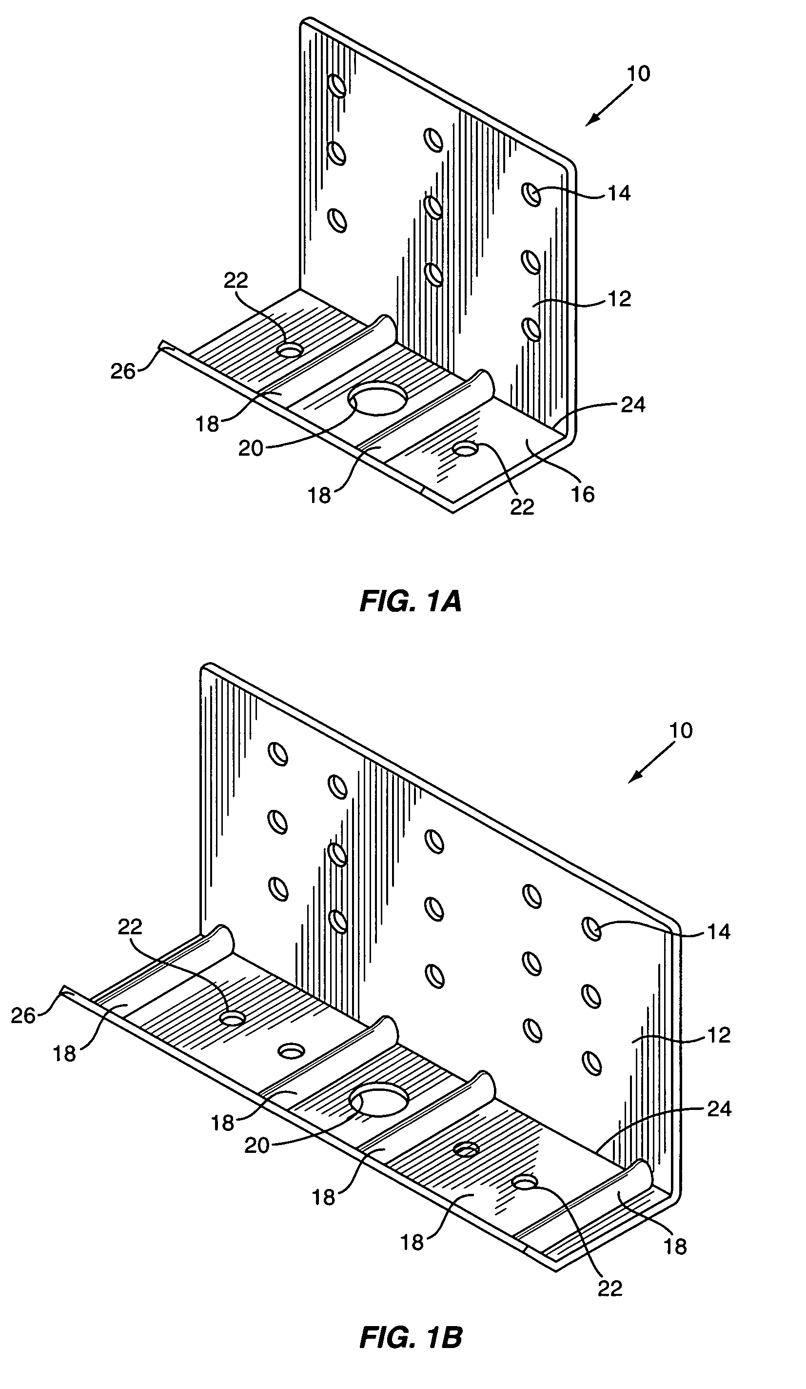
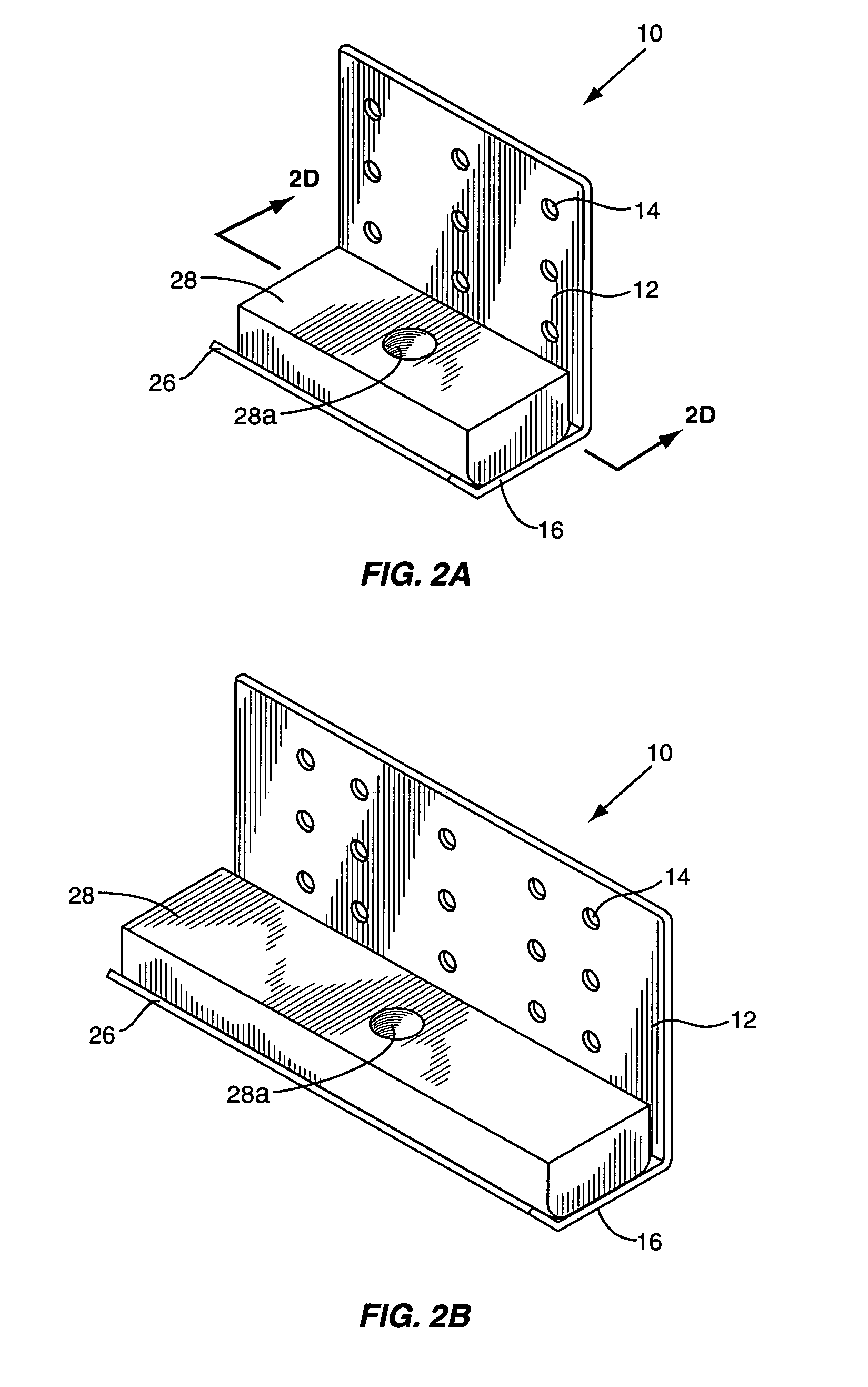
[0019]Turning to a description of the connector 10, as seen in FIGS. 1A and 1B, the connector 10 includes a connecting plate 12. The connecting plate 12 includes a series of openings 14 that are designed to receive fasteners such as screws or bolts that act to secure the connector 10 to a vertical support member such as a building stud indicated generally by the numeral 50 in FIGS. 3 and 4.

[0020]Extending from the connecting plate 10 is a base plate 16. Base plate 16 includes a series of reinforcing ...


PUM


Abstract

A connector or clip is provided for connecting a metal stud or other member to a support structure. The connector or clip includes a connecting plate for connecting to the stud or other member. A base plate extends from the connecting plate and is adapted to mount to the support structure. A juncture or fold line is defined between the connecting plate and the base plate. One or more ribs are formed in the base plate and extend generally perpendicular to the juncture. In one embodiment, an upturned edge is formed along one side of the base plate opposite the juncture. Further, a reinforcing member is adapted to be secured to the base plate such that both the base plate and reinforcing member can be secured to an adjacent support surface or structure via a connecting fastener.

Description

FIELD OF THE INVENTION[0001]The present invention relates to metal connectors and more particularly to a connector for connecting a metal building stud to an underlying or overlying support structure.BACKGROUND OF THE INVENTION[0002]In recent years, cold-formed steel framing for both residential and commercial applications has grown at a tremendous rate. Today, engineers, architects and contractors appreciate that light steel framing is a better value than more traditional materials such as masonry or wood.[0003]Light steel framing is ideal for floors, roofs, support structures for finishes, non-load bearing walls, and even load-bearing walls up to approximately nine stories. With wall systems, whether they are load-bearing or non load-bearing, it is customary to use connectors or clips to secure individual metal studs to overlying and / or underlying support structures. Various connector or clip designs are known. For example, it is known to use simple L-shaped connector designs to i...

Claims


Application Information

Patent Timeline
Patent Type & Authority Patents(United States)
IPC IPC(8): E04C5/12
CPCE04B2/58E04B2001/2415E04B2001/2448Y10S248/903Y10T403/73Y10T403/4602E04B2001/2463F16B2200/67
Inventor DIGIROLAMO, EDWARD R.TORRES, MICHAEL L.
Owner THE STEEL NETWORK
Why Eureka
Try Eureka