Rapid-change lock

a technology of cylinder locks and lock parts, applied in the field of cylinder locks, can solve the problems of affecting the security of the organization, the subsequent occupants or tenants cannot be secure in their persons and property, and the control of one or more, and achieve the effect of rapid change of positioning and without disassembly of the lock assembly

Inactive Publication Date: 2009-05-19
JANAKA PARTNERSHIP
View PDF101 Cites 21 Cited by
  • Summary
  • Abstract
  • Description
  • Claims
  • Application Information

AI Technical Summary

Benefits of technology

[0019]The present invention solves the problems and eliminates the drawbacks of locks as described above in the background of the invention. The present invention does so by providing both an adaptable or changeable lock and a method of using the lock in order to reprogram the lock to accept a second key having a different top contour than a first key. The present invention provides a lock that pe

Problems solved by technology

When keys and locks formed by the second method are involved, it is not sufficient for opening the lock that one have a key having a top edge contour appropriate to the lock; the key must also include an appropriate longitudinal contour of grooves and/or ridges.
Over the course of time, the security of an organization may become compromised by the loss of control of one or more of the tenant keys.
For example, in apartment buildings, hotels, or motels, a guest or renter may leave and inadvertently or intentionally retain a key.
When this occurs, subs

Method used


Image

  • Rapid-change lock
  • Rapid-change lock
  • Rapid-change lock

Examples


first embodiment

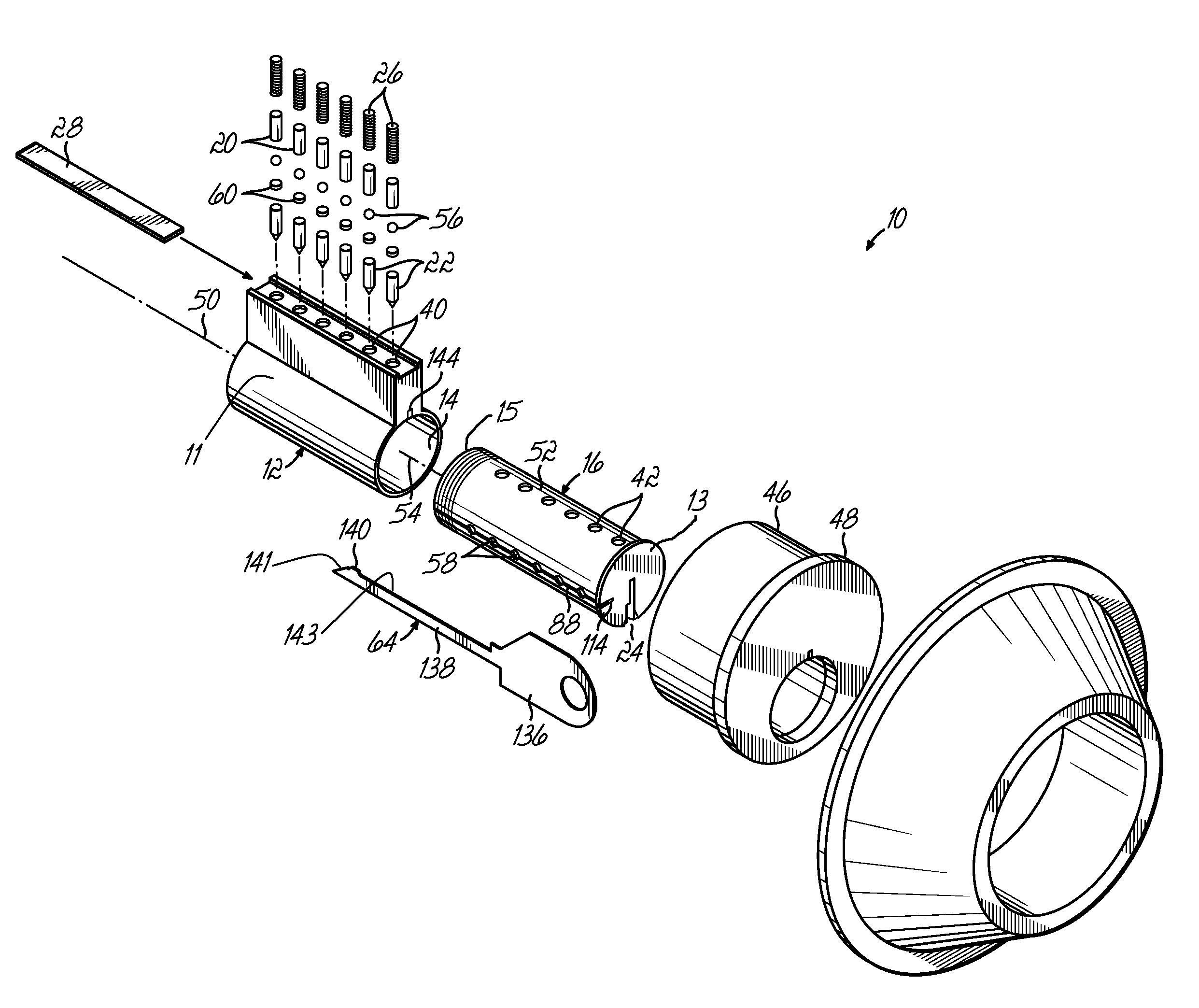
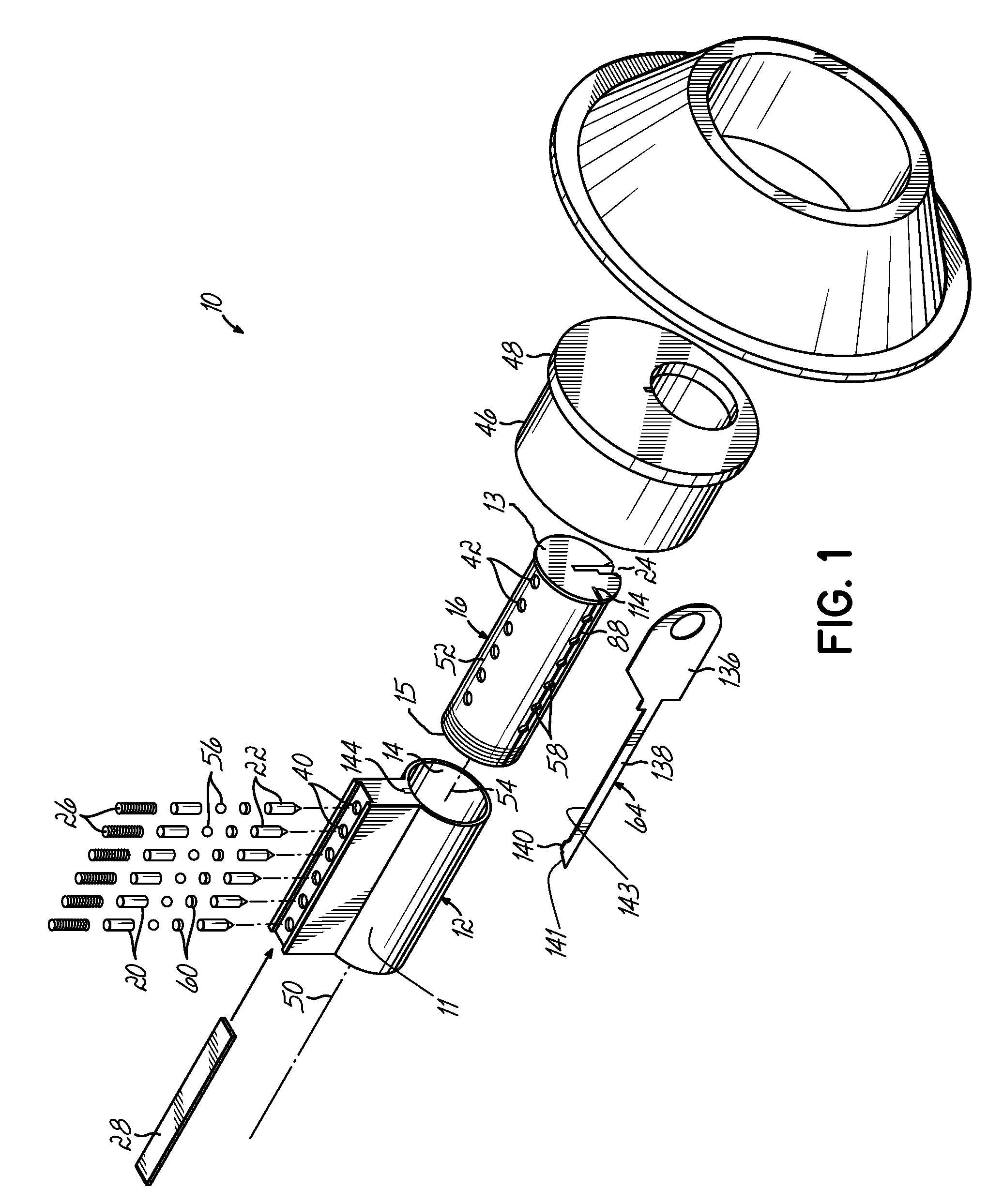
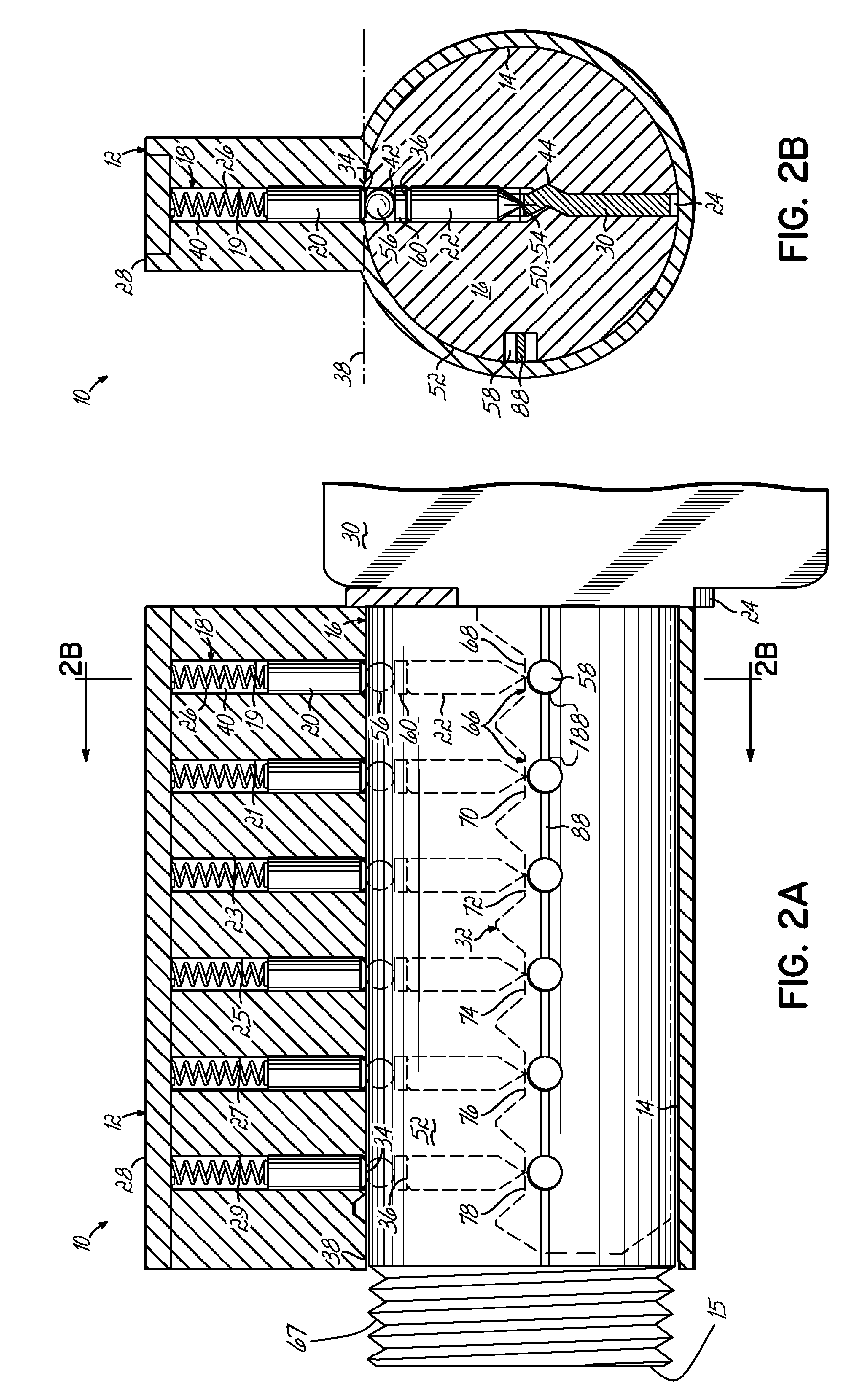
[0138]Referring now to FIGS. 2A-13D, the lock 10 of the present invention is illustrated. This illustrated embodiment of the present invention allows an operator to change the configuration of drivers 20, tumblers 22, and change balls 56 of a lock that operates with a first user key 30, to accept and render operable a second user key 62, and render inoperable the first key 30, without the use of a change tool 64 (see FIG. 1). Thus, the second key 62 is used to change the configuration of drivers 20, tumblers 22, and change balls 56 in the lock 10 in order to foreclose the use of the first key 30, without removal and disassembly of the lock itself. A subset of user keys can be provided wherein the use of each subsequent operating key can reconfigure or re-key the lock 10 to foreclose any previous operating key from operating the lock 10. This progression can be determined by the differing top edge contours 32 of each of the keys. As an operator progresses through using each key of th...

second embodiment

[0173]In another alternative of the invention, the subset of keys can be configured so that each user key in the subset can raise four of the change balls above the shear line 38 of the lock 10 when inserted into the keyway 24. Each user key of the subset of user keys is configured with four raised contour locations 66, wherein no two keys exhibit the same staggered pattern of four raised contour locations 66. The maximum number of keys in the four-raised-contour subset is the same as that number for the two-raised-contour subset of keys described herein before. The four-raised-contour key has an added advantage of reducing the possibility of “incidental keying”. This situation can occur when a lock is opened with a key from outside the subset of keys having one or more contour positions with a slightly different height. The slightly different contour height can cause the centerline of a change ball to be unintentionally raised above the shear line 38 when that key is inserted into ...

third embodiment

[0181]Referring now to FIGS. 23A-28B, wherein like components are referenced by like numbers, an illustrated third embodiment of the present invention is shown comprising at least one memory block associated with a retainer cavity. The memory block 90 is disposed in the plug 16 of the lock 10 and is configured to intersect the change slot 88 and retainer cavities 58. The memory block 90 prevents a user key other than the currently operable user key from being used to alter the driver, tumbler, and change ball configurations in the lock 10 in an unauthorized fashion. The memory block 90 accomplishes this by partially blocking the openings to the retainer cavities 58, so that change balls 56 cannot fit past the opening and into the retainer cavities 58. An authorized user may then insert a change tool 64 to move the memory block 90 away from the change slot 88 and expose the full diameter of the openings of the retainer cavities 58.

[0182]The lock 10 having a memory block 90 is shown i...


PUM


Abstract

A changeable lock assembly suitable for re-keying a lock without disassembly of the lock. The assembly includes a housing having a bore therein, and a plug rotatably mounted in the bore. The plug includes a longitudinal axis and a keyway. The keyway is adapted to receive at least a first user key and a second user key. The lock further includes a change member movable within the lock between a first position to a second position. The change member can move solely in response to operation of the second key. Thus, when the change member is in the first position, the first key operates the lock, and when the change member is in the second position, the first key does not operate the lock. The lock assembly can also employ a change tool that, when inserted into a change slot, can move a change ball from the second position back to the first position.

Description

CROSS REFERENCE TO RELATED APPLICATIONS[0001]This application claims the benefit of U.S. Provisional Application No. 60 / 469,025, filed May 8, 2003 and U.S. Provisional Application No. 60 / 481,298, filed Aug. 27, 2003.BACKGROUND OF INVENTION[0002]This invention relates generally to cylinder locks, and more particularly to a programmable cylinder lock which allows for adapting the lock to operate upon insertion of a key having a different configuration than a key to which the lock was originally adapted.[0003]In many organizations, such as businesses, apartment buildings, hotels, schools, etc., it is generally desirable to customize the locks to the particular organization. There are two general methods by which keys and locks may be customized. The first involves reconfiguring the drivers and tumblers in the lock so that a key with a particular top edge contour may operate the locks of the organization. The second involves configuring the keyways in the locks to accept keys having a u...

Claims


Application Information

Patent Timeline
IPC IPC(8): E05B27/04E05B19/00E05B27/00E05B35/08
CPCE05B27/005E05B19/0017E05B35/083Y10T70/7463Y10T70/7469Y10T70/7605Y10T70/7729Y10T70/7734Y10T70/774Y10T70/7746Y10T70/7751E05B27/02
Inventor HERDMAN, RODRICK A.
Owner JANAKA PARTNERSHIP
Why Eureka
Try Eureka