Liquid discharge head, and method of manufacturing liquid discharge head

a liquid discharge head and liquid discharge technology, applied in the direction of electrical equipment, printing, semiconductor devices, etc., can solve the problems of high pressure, damage to the electrical connection portion, exposed, etc., and achieve the effect of reducing the amount of sealing resin protruding

Inactive Publication Date: 2009-05-19
CANON KK
View PDF15 Cites 59 Cited by
  • Summary
  • Abstract
  • Description
  • Claims
  • Application Information

AI Technical Summary

Benefits of technology

[0012]Still another object of the present invention is to provide a method of manufacturing a liquid discharge head, comprising: a step of electrically connecting a discharge element substrate including a discharge port for discharging liquid and a discharge energy generating element, with an electrical wiring substrate; a step of applying a sealing resin to an electrical connection portion between the discharge element substrate and the electrical wiring substrate; and a step of reducing a protrusion amount of the sealing resin by depressing a mold member before the sealing resin applied to the electrical connection portion is cured.

Problems solved by technology

Furthermore, according as the size of a liquid droplet becomes small, a possibility of being influenced by disturbances such as air stream and the like becomes high if a discharge distance of the ink droplet is long.
However, in this case, if the height of the sealant is suppressed by a conventional method, there occurs a problem that the electrical connection portion is damaged and / or exposed.

Method used


Image

  • Liquid discharge head, and method of manufacturing liquid discharge head
  • Liquid discharge head, and method of manufacturing liquid discharge head
  • Liquid discharge head, and method of manufacturing liquid discharge head

Examples


embodiment 1

[0062]A first embodiment of the present invention will be explained with reference to FIGS. 1 to 21B.

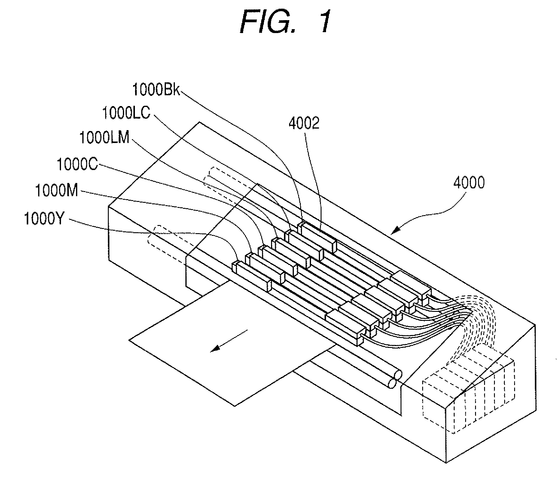
[0063]As shown in FIG. 1, the main body of a recording device 4000 (for convenience, called a recording device main body 4000 hereinafter) acting as a liquid discharge device according to the embodiment of the present invention is equipped with, for example, recording heads of six colors in correspondence with recording of photographic image quality. A recording head 1000Bk is the recording head for a black ink, a recording head 1000C is the recording head for a cyan ink, a recording head 1000M is the recording head for a magenta ink, a recording head 1000Y is the recording head for an yellow ink, a recording head 1000LC is the recording head for a light cyan ink, and a recording head 1000LM is the recording head for a light magenta ink. It should be noted that, in the following, the recording heads 1000Bk, 1000C, 1000M, 1000Y, 1000LC and 1000LM might collectively be called simply as...

embodiment 2

[0105]Subsequently, a second embodiment of the present invention will be explained with reference to FIGS. 22A to 29B.

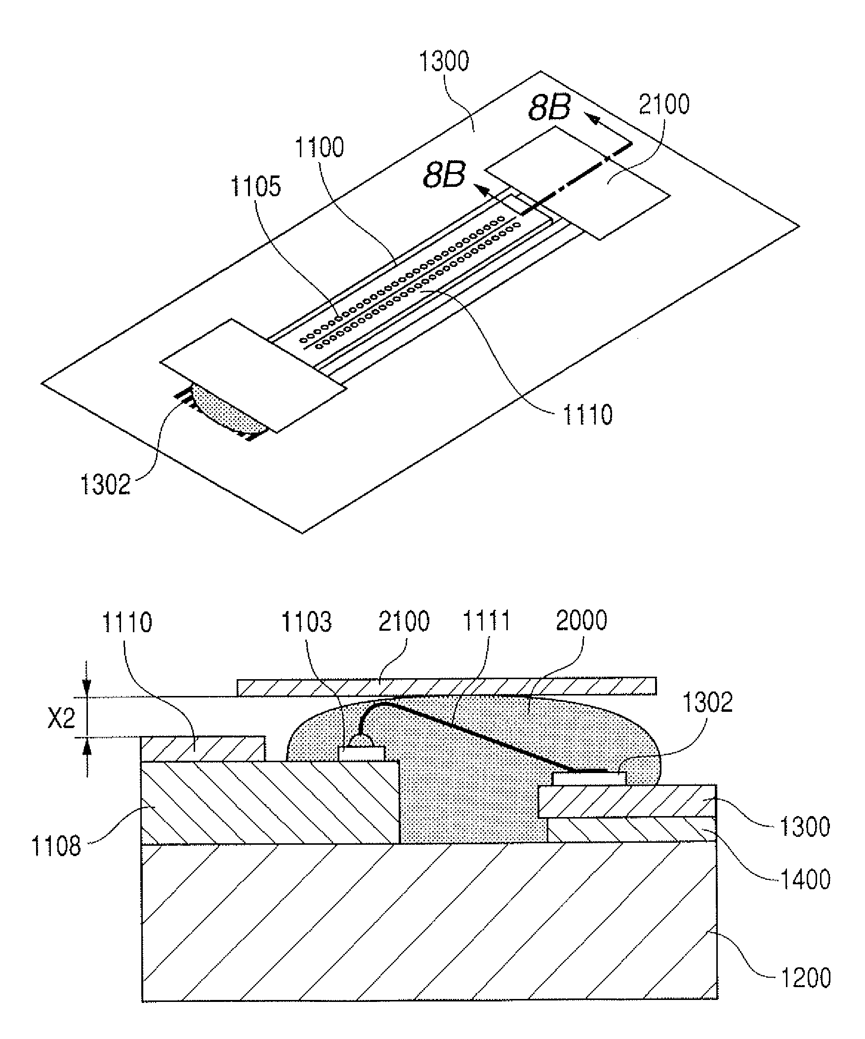
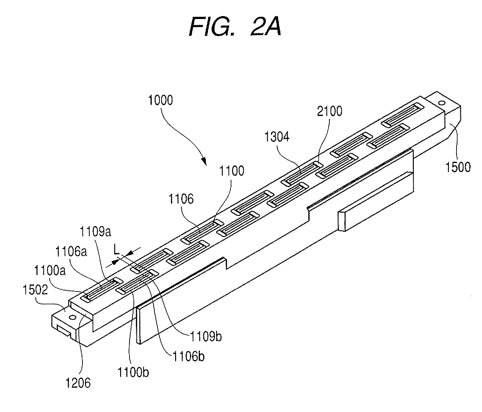
[0106]FIG. 22A is the perspective view showing one recording element substrate 1100 of the recording head 1000 and the enlarged periphery thereof, and FIG. 22B is the cross sectional view along the line 22B-22B shown in FIG. 22A. Here, it should be noted that each of FIGS. 28 and 29 is likewise composed of the perspective view and the cross sectional view.

[0107]Incidentally, although a method using wire bonding, a method using inner lead bonding (ILB), a method using an anisotropic conductive film (ACF) or the like is practically used as a concrete electrical connection method, it should be noted that the present embodiment is applicable to any method.

[0108]An electrode 1103, through which inputting / outputting of electrical signals and supplying of electrical power are executed for the recording element substrate 1100, and an electrical wiring substrate 1300 are mutu...

embodiment 3

[0147]Subsequently, a third embodiment of the present invention will be explained with reference to FIGS. 30A to 43B.

[0148]FIG. 30A is the perspective view showing one recording element substrate 1100 of the recording head 1000 and the enlarged periphery thereof, and FIG. 30B is the cross sectional view along the line 30B-30B shown in FIG. 30A. Here, it should be noted that each of FIGS. 31 and 43 is likewise composed of the perspective view and the cross sectional view.

[0149]Incidentally, although a method using wire bonding, a method using inner lead bonding (ILB), a method using an anisotropic conductive film (ACF) or the like is practically used as a concrete electrical connection method, it should be noted that the present embodiment is applicable to any method. Incidentally, when the wire bonding method is executed, the extension portion of a cover film 2100 of an electrical wiring substrate 1300 is folded and temporarily fixed to the position apart from the electrical connect...


PUM


Abstract

A liquid discharge head comprises: a discharge element substrate including a discharge port for discharging liquid and a discharge energy generating element; an electrical wiring substrate for inputting an electrical signal to the discharge energy generating element; a supporting mechanism for supporting the discharge element substrate and the electrical wiring substrate; an electrical connection portion for electrically connecting the discharge element substrate with the electrical wiring substrate; a sealant coated on the electrical connection portion; and a film-like member coating the electrical connection portion along the shape of the electrical connection portion through the sealant. Thus, the liquid discharge head resultingly includes the electrical connection portion on which the height of the sealant is suppressed and lowered sufficiently so as to prevent a problem that the electrical connection portion is damaged and / or exposed due to its height.

Description

BACKGROUND OF THE INVENTION[0001]1. Field of the Invention[0002]The present invention relates to a liquid discharge head which discharges liquids such as ink or the like, and a method of manufacturing the relevant liquid discharge head.[0003]2. Description of the Related Art[0004]As an energy generating element (liquid discharge element) which generates energy for discharging liquids from a liquid discharge port provided on a liquid discharge head, the element which uses an electromechanical transducer such as a piezoelectric element or the like and the element which uses an electrothermal transducer for heating liquids through a heat generating resistor are used.[0005]Besides, discharge energy generating elements, circuits for driving the discharge energy generating elements, a temperature sensor and the like are formed on a liquid discharge substrate. Further, to drive the liquid discharge elements at appropriate timing and to read information from the temperature sensor, the liqu...

Claims


Application Information

Patent Timeline
Patent Type & Authority Patents(United States)
IPC IPC(8): B41J2/205
CPCB41J2/14072B41J2/1603B41J2/1623B41J2/1637H01L2224/8592B41J2202/20H01L2224/48465H01L2224/48091H01L2924/00014H01L2924/00B41J2/01B41J2/015
Inventor YASUDA, JUNJITAKANO, KATSUHIKOSUEOKA, MANABUTAKENAKA, SHIGEONISHIKAWA, KATSUMASAUDAGAWA, KENTAHIROSAWA, TOSHIAKI
Owner CANON KK
Why Eureka
Try Eureka