
Alternator

a technology of alternators and alternators, applied in the direction of electric generator control, dynamo-electric converter control, control systems, etc., can solve the problems of increasing the electrical power consumption of vehicles, increasing the tendency of increasing electrical power consumption, and unable to achieve sufficient electric power generation in vehicles at present, so as to achieve stable operation and suppress heat evolution in excitation wiring

Inactive Publication Date: 2009-05-19
DENSO CORP
View PDF29 Cites 11 Cited by
  • Summary
  • Abstract
  • Description
  • Claims
  • Application Information

AI Technical Summary

Benefits of technology

This design increases electric power generation capacity without additional weight or size, stabilizes operation over long periods, and reduces heat in the excitation winding, improving feasibility for vehicle integration.

Problems solved by technology

Electronics devices for improving safety and comfortable driving have recently come to be loaded on vehicles, and this tends to increase electrical power consumption in vehicles.
These measures for improving fuel consumption, however, also require suitable electronics devices, so that the tendency of increasing electrical power consumption has been reinforced.
In this way, sufficient electric power generation is unlikely to be achieved in vehicles currently.
However, in an alternator, in general, electric current equal to or more than a current value determined by battery charge voltage cannot be supplied to the excitation winding.
Therefore, it is not easy to increase a maximum output current.
This approach, however, may increase the output current, while deteriorating feasibility of loading the alternator on a vehicle and impeding reduction in the weight of the vehicle, and thus may raise problems if put into practice.
This configuration has a problem that various additional parts, such as a wiring, a transformer, a rectifier and a switch, are required.
Further, the separately provided power source which is used only for exciting the alternator is so large that it constitutes a factor for impeding weight reduction of a vehicle.
Thus, when electric power is generated in a high-speed region of engine revolution (“a high-speed region of engine revolution” hereinafter abbreviated as “a high-speed region”) by utilizing this configuration, the voltage applied to the excitation winding (i.e. the voltage boosted and rectified by the three-phase transformer) becomes so large that, although the current flowing through the excitation winding is increased, heat built up in the excitation winding itself is also problematically increased.
As a result, deterioration is accelerated in the insulating film of the copper wire constructing the excitation winding to resultantly shorten the life of the insulating film, making it difficult to provide an operation which is stable for a long period of time.
Moreover, although the DC-DC converter has a large size and contributes to increasing the amount of power generation, it does not satisfy the requirements of reduced size and weight of a vehicle.
Comparing with a self-excitation type configuration, the separate-excitation type configuration reduces current that can be supplied to the excitation wiring, whereby the output current of the alternator is problematically reduced.

Method used


Image

  • Alternator
  • Alternator
  • Alternator

Examples


first embodiment

1. First Embodiment

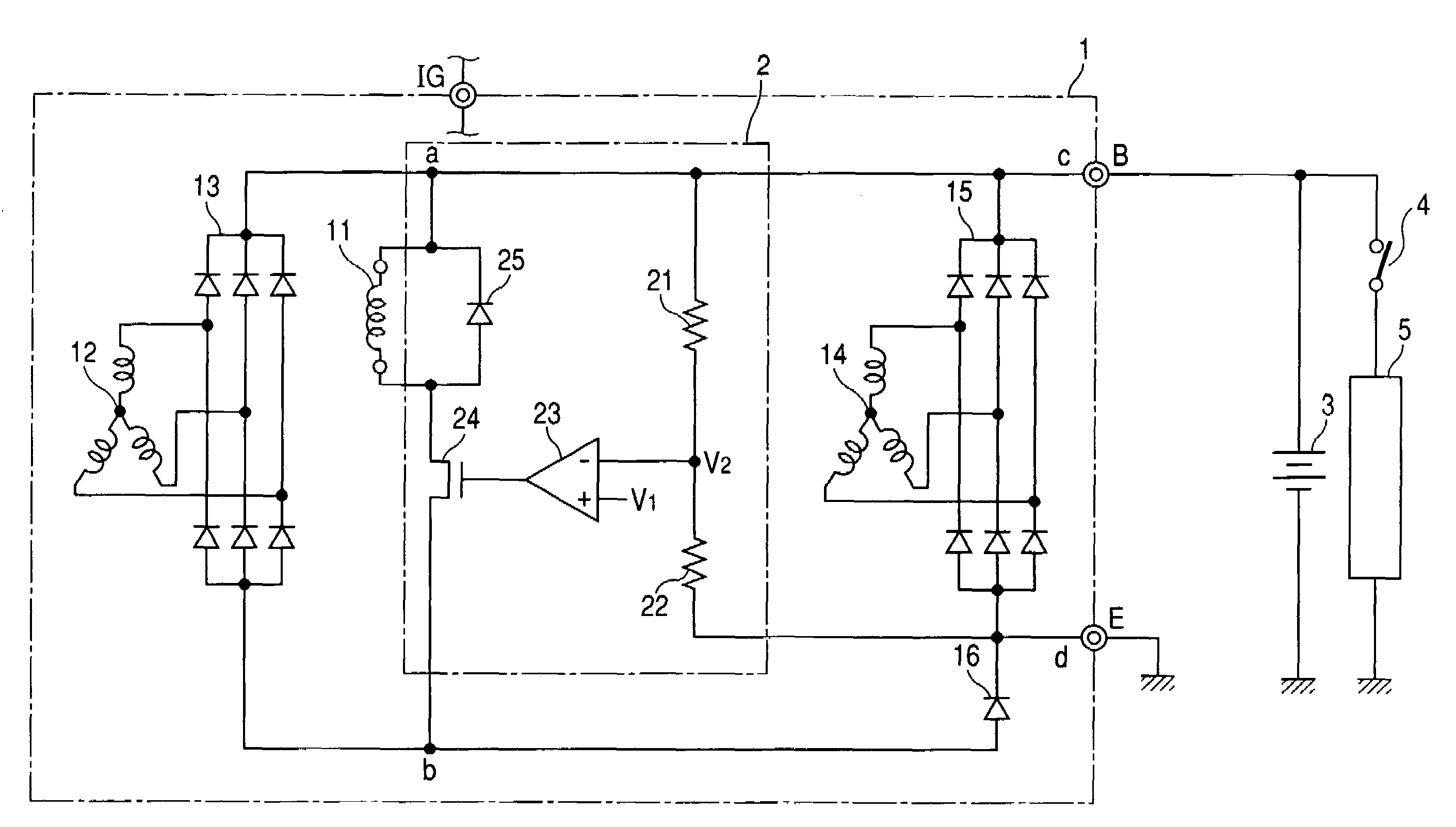
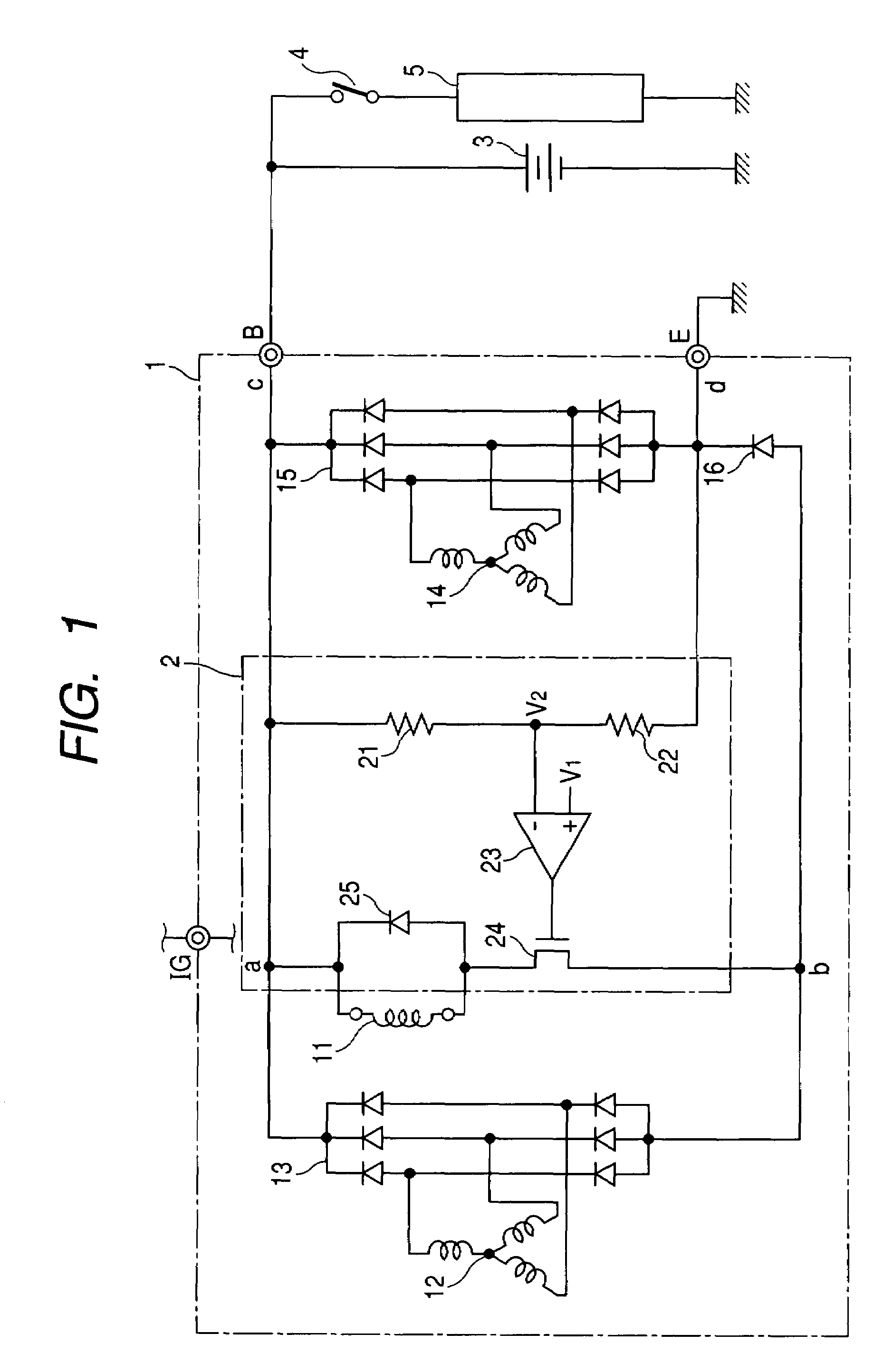
[0029]With reference to FIG. 1, an alternator 1 according to a first embodiment of the present invention is described below in the order of its configuration, operation and advantages.

1.1 Configuration

[0030]FIG. 1 is a block diagram showing the configuration of the alternator 1 according to the first embodiment from an electrical circuit view. FIG. 1 also shows a state of electrical connections between the alternator, a battery, etc.

[0031]As shown in FIG. 1, the alternator 1 comprises an excitation winding 11, an excitation armature winding 12, an excitation rectifier 13 (hereinafter referred to as a “first rectifier 13”), an output armature winding 14, an output rectifier 15 (hereinafter referred to as a “second rectifier 15”), a rectifying element 16 and a power generation unit 2.

[0032]The excitation armature winding 12 is provided for exciting the excitation winding 11 so as to enable the alternator 1 to generate electric power, while the output armature windin...

second embodiment

2. Second Embodiment

[0058]Referring to FIG. 2, a second embodiment of the present invention will now be described.

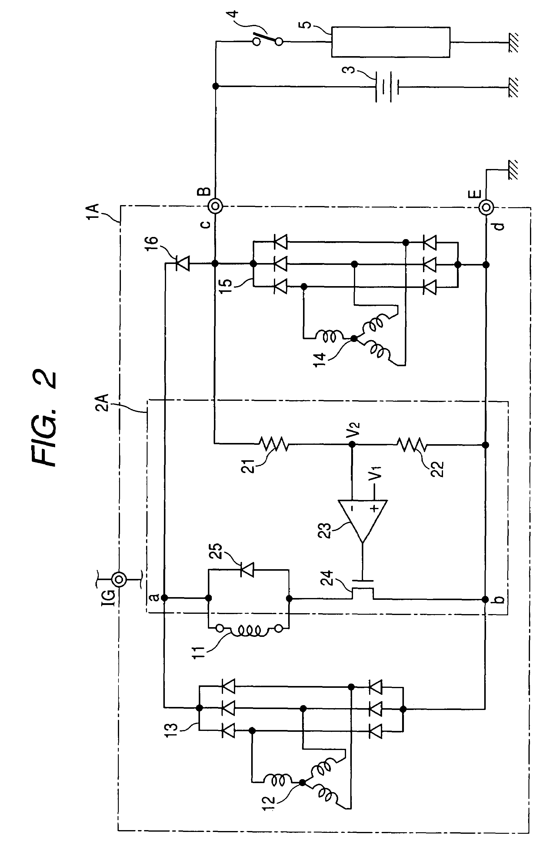
[0059]FIG. 2 is a block diagram showing a configuration of an alternator according to a second embodiment of the present invention. FIG. 2 also shows a state of electrical connection between the alternator, a battery, etc. In the present embodiment, the identical or similar components or processes to those of the first embodiment are given the same references as in the first embodiment for the sake of simplification or omission of explanation.

[0060]As shown in FIG. 2, an alternator 1A of the present embodiment comprises the excitation winding 11, the excitation armature winding 12, the first rectifier (excitation rectifier) 13, the output armature winding 14, the second rectifier (output rectifier) 15, the rectifying element 16 and a power generation control unit 2A.

[0061]The alternator 1A of the present embodiment shown in FIG. 2 is different from the alternator 1 of th...

third embodiment

3. Third Embodiment

[0067]Referring to FIG. 3, a third embodiment of the present invention will now be described.

[0068]In the alternator 1 and the alternator 1A of the first and the second embodiments described above, respectively, the first rectifier 13 and the second rectifier 15 have been electrically separated by employing the rectifying element 16, and the initial excitation current has been supplied to the excitation winding 11 through this rectifying element 16 from the battery 3. However, such a rectifying element can be omitted in a circuit configuration in which electric power can be generated with the rotation of the rotor without having to supply the initial excitation current (e.g., a circuit configuration employing a rotor which uses both a permanent magnet and an electromagnet). An alternator 1B of a third embodiment exemplifies such a circuit configuration.

[0069]FIG. 3 is a block diagram showing a configuration of the alternator 1B of the third embodiment. FIG. 3 also...


PUM


Abstract

An alternator comprises: an output rectifier converting AC voltage produced in an output armature winding into DC and supplying the DC electric power to a rechargeable battery and a current consumer; an excitation rectifier which is electrically separated from the output rectifier to convert AC voltage produced in an excitation armature winding into DC; and a power generation control unit. The power generation control unit compares the output voltage of the output rectifier or the terminal voltage of the battery with a predetermined reference voltage and controls current supplied to an excitation winding to which the DC voltage outputted from the excitation rectifier is applied, based on the comparison result.

Description

CROSS-REFERENCE TO RELATED APPLICATION[0001]This application is based on and claims the benefit of priorities from earlier Japanese Patent Application No. 2006-031282 filed Feb. 8, 2006, and Japanese Patent Application No. 2006-240470 filed Sep. 5, 2006, the description of which is incorporated herein by reference.BACKGROUND OF THE INVENTION[0002]1. Technical Field of the Invention[0003]The present invention relates to an alternator, and in particular, to an alternator to be loaded on a passenger car or a truck, for example.[0004]2. Related Art[0005]An alternator for a vehicle (hereinafter referred to just as an “alternator”) is loaded on an engine to charge a battery or supply current to on-vehicle machinery which imposes electrical loading (hereinafter referred to as a “current consumer”).[0006]For example, as described in Japanese Patent Application Laid-Open No. 3-060338, an alternator generally includes a rotor, an excitation winding, a stator, a rectifier and a voltage regulat...

Claims


Application Information

Patent Timeline
Patent Type & Authority Patents(United States)
IPC IPC(8): H02P9/00
CPCH02P9/305
Inventor AOYAMA, TORU
Owner DENSO CORP
Learn More