Projection type image display

a projection type and image technology, applied in the direction of printers, instruments, camera focusing arrangement, etc., can solve the problems of misaligning the screen-projected image in a vertical direction, affecting the accuracy of projection, and neither of the above two patent documents contains any considerations concerning the increase in the amount of distortion

Inactive Publication Date: 2009-05-19
MAXELL HLDG LTD
View PDF11 Cites 19 Cited by
  • Summary
  • Abstract
  • Description
  • Claims
  • Application Information

AI Technical Summary

Benefits of technology

[0007]The present invention was made with the above problems in view, and an object of the invention is to provide a projection type image display adapted such that trapezoidal distortion and aberration of a projected image due to oblique projection onto a projection screen can be effectively corrected with a compact configuration and such that any effects caused by environmental changes can be reduced. Another object of the invention is to provide a projection optical unit for the projection type image display.

Problems solved by technology

The aberration correction involved, however, is likely to misalign the screen-projected image in a vertical direction.
Furthermore, neither of the above two patent documents contains any considerations concerning increases in the amount of distortion due to the deformation of the free-form surface mirror in connection with changes in ambient environment.

Method used


Image

  • Projection type image display
  • Projection type image display
  • Projection type image display

Examples


Embodiment Construction

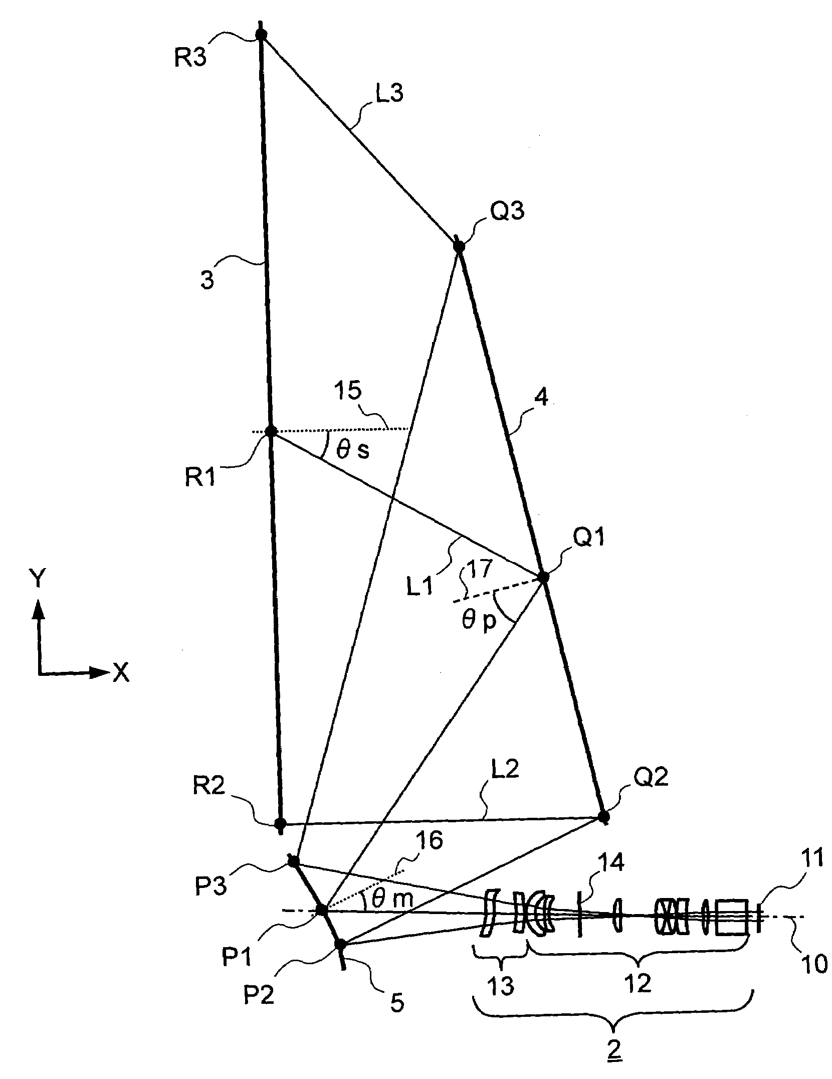
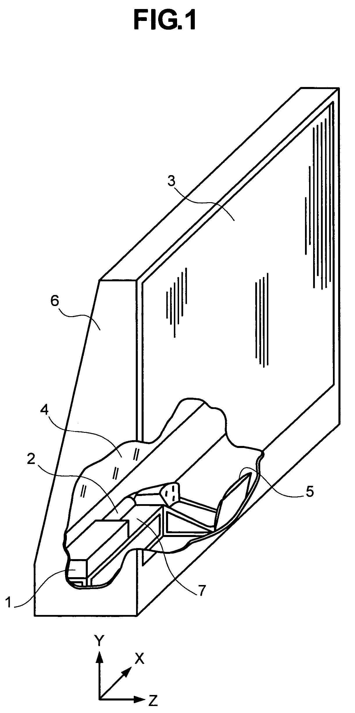
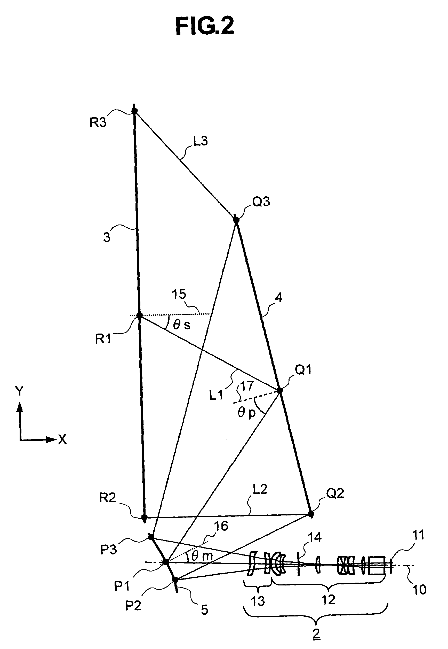
[0024]Embodiments of the present invention will be described hereunder using the accompanying drawings. FIG. 1 is a perspective view showing an embodiment of an image display according to the present invention, partially showing its interior, wherein reference number 1 denotes an image generator, 2 a projection lens section, 3 a projection screen, 4 a planar reflecting mirror, 5 a free-form surface mirror, 6 an enclosure, and 7 an optics base.

[0025]In FIG. 1, the image generator 1 adapted to form and display an image on its small-size display screen uses an optical modulator such as a reflection-type or transmission-type liquid-crystal panel or a display element including a plurality of micromirrors. The display screen may be a projection cathode-ray tube. The image that has been displayed on the display screen of the image generator 1 is enlarged when displayed on the projection screen 3. In an optical path of image light from the display screen to the projection screen 3, the imag...


PUM


Abstract

An image that has been displayed on the display screen of an image generator is first passed through a projection lens section consisting of a front group and a rear group. Next after being reflected on the reflecting surface of a free-form surface mirror, the image is further reflected by a planar reflecting mirror and then obliquely projected from the lower section of a projection screen onto the screen. The front group of the projection lens section is provided for enlarging the image. In order to correct aberration due to oblique projection onto the projection screen, the rear group uses a free-form surface lens that forms a concave shape with respect to the exit side of light from the lens. The free-form surface mirror corrects trapezoidal distortion due to oblique projection onto the projection screen. The free-form surface lens in the rear group of the projection lens section can accommodate changes in environmental conditions by using one edge as a reference edge and rendering the other edge expandable. The free-form surface mirror can likewise use one edge as a reference edge and render the other edge expandable. For adjustment, the free-form surface mirror can also be pivoted about the reference edge.

Description

BACKGROUND OF THE INVENTION[0001]The present invention relates generally to projection type image displays that make an enlarged projection-screen display of an image displayed on a display screen of an image display element, and to projection optical units for the image displays. More particularly, the invention concerns a projection type image display that makes an enlarged projection-screen display of an image displayed on a display screen of an image display element, and to a projection optical unit for the image display.[0002]Projection type image displays that make an enlarged projection-screen display of an image displayed on a display screen of an image display element which uses a reflection or transmission type of liquid-crystal panel or micromirror are needed to be reduced in depth for compactness, as well as to be able to obtain an enlarged image of a sufficient size on the projection screen. Japanese Patent Laid-Open No. 2001-264627, for example, discloses a projection ...

Claims


Application Information

Patent Timeline
Patent Type & Authority Patents(United States)
IPC IPC(8): G03B21/28G02B3/00G02B9/00
CPCG03B21/10G03B21/14G03B21/28H04N5/74G03B21/147
Inventor YOSHIKAWA, HIROKIHISADA, TAKANORIOHISHI, TETSUHIRATA, KOJIOGURA, NAOYUKI
Owner MAXELL HLDG LTD
Why Eureka
Try Eureka