Power transmitting apparatus, power switching apparatus, and driving apparatus of multi-function machine using the same

a multi-function machine and power transmission technology, applied in the direction of printing mechanisms, instruments, gearing, etc., can solve the problems of deterioration of power transmission performance between, increase in fabrication cost, etc., and achieve the effect of reducing fabrication cos

a multi-function machine and power transmission technology, applied in the direction of printing mechanisms, instruments, gearing, etc., can solve the problems of deterioration of power transmission performance between, increase in fabrication cost, etc., and achieve the effect of reducing fabrication cos

US7536129B2Inactive Publication Date: 2009-05-19HEWLETT PACKARD DEV CO LP

Image

  • Power transmitting apparatus, power switching apparatus, and driving apparatus of multi-function machine using the same
  • Power transmitting apparatus, power switching apparatus, and driving apparatus of multi-function machine using the same
  • Power transmitting apparatus, power switching apparatus, and driving apparatus of multi-function machine using the same

Examples


Embodiment Construction

[0067]Reference will now be made in detail to the present aspects of the present invention, examples of which are illustrated in the accompanying drawings, wherein like reference numerals refer to the like elements throughout. The aspects are described below in order to explain the present invention by referring to the figures.

[0068]Hereinafter, a driving apparatus of a multi-function machine according to the present invention will be described in greater detail with reference to the accompanying drawings.

[0069]FIG. 6 shows a multi-function machine to which a driving apparatus 100, according to an aspect of the present invention, is applied.

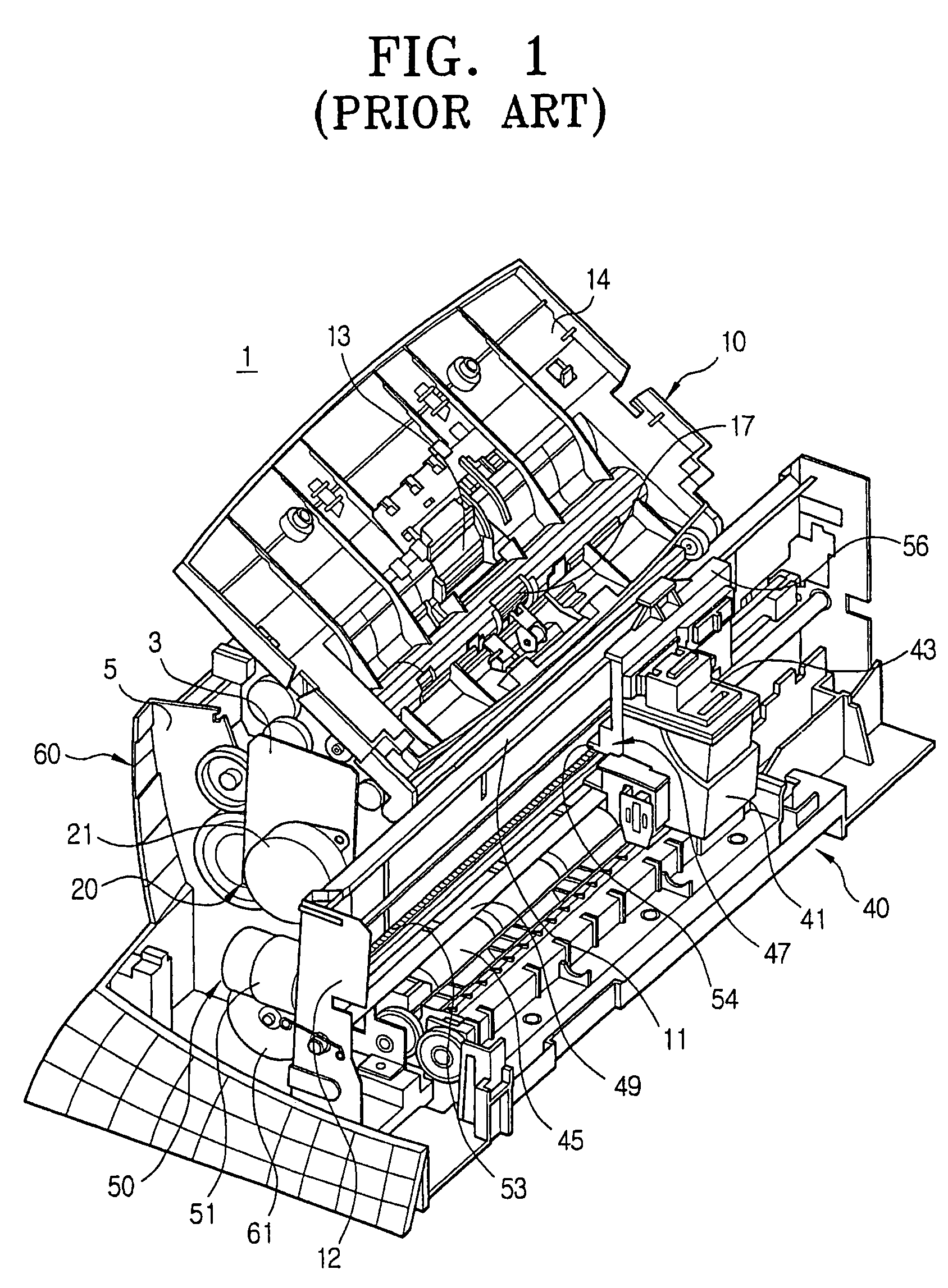
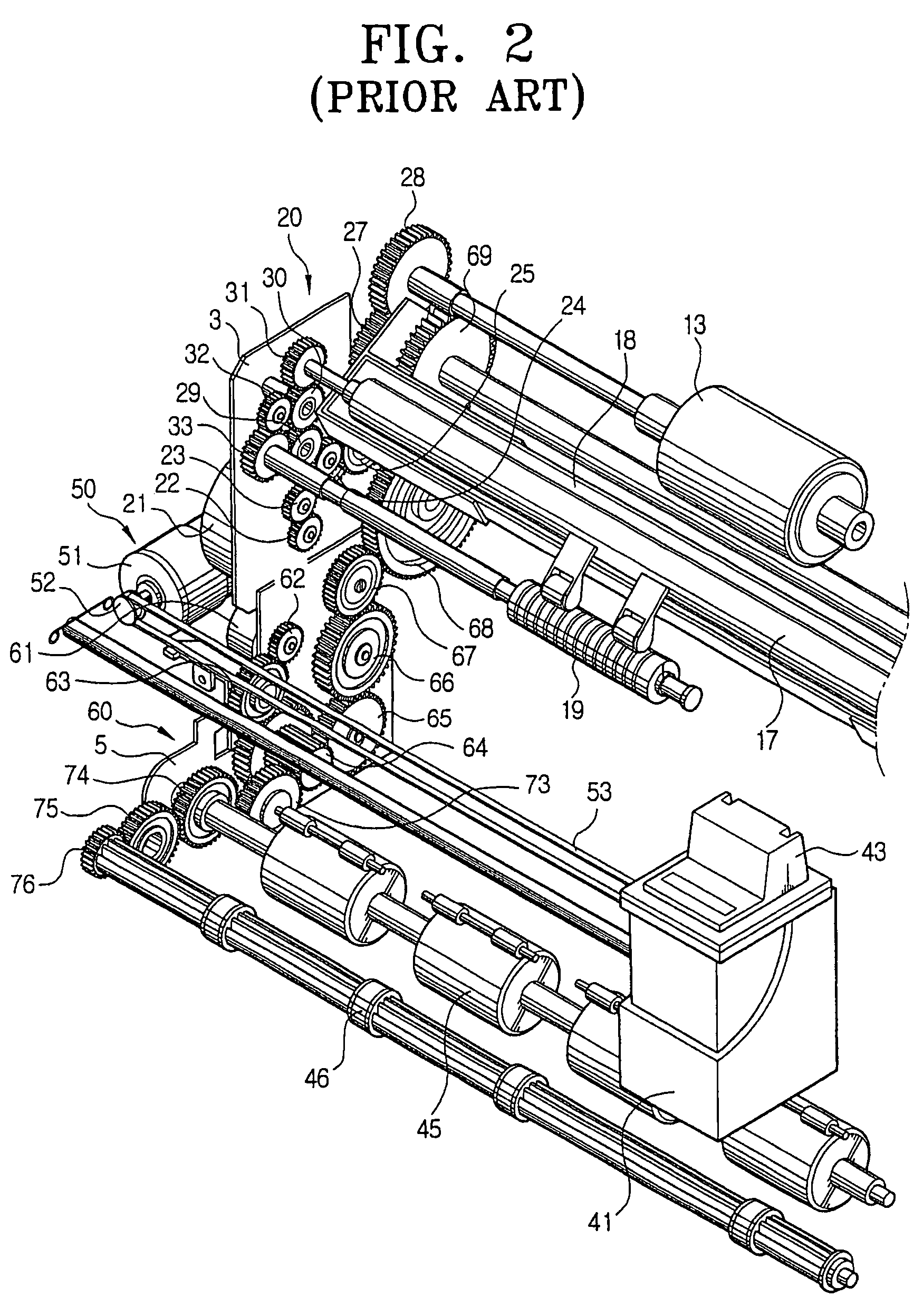
[0070]Like as the conventional multi-function machine 1 explained with reference to FIGS. 1 and 2, the multi-function machine has a scanner unit 110 to scan data recorded on a sheet of document D, and a printer unit 140 to print the data on the sheet for an output, as basic components. According to the design, the multi-function machine further i...


PUM


Abstract

A driving apparatus of a multi-function machine includes a scanner unit scanning data recorded on a sheet of document and a document transport part to transport the sheet of document. A printer unit prints data on a sheet of paper for an output and includes a carrier including a print head with an ink jet nozzle mounted thereon to carry out the printing operation by moving the print head. The driving apparatus includes a driving motor, a scanner driving part driving the scanner unit, a printer driving part driving the printer unit, and a power switching part disposed with the driving motor, the scanner driving part, and the printer driving part. The power switching part selectively transmits a power of the driving motor to at least one of the scanner driving part and the printer driving part.

Description

CROSS-REFERENCE TO RELATED APPLICATIONS[0001]This application is a continuation of application Ser. No. 10 / 715,402 filed Nov. 19, 2003 and claims the benefit of Korean Application Nos. 2002-86837, 2002-86838, and 2002-86841, filed Dec. 30, 2002, in the Korean Intellectual Property Office, the disclosures of which are incorporated herein by reference.BACKGROUND OF THE INVENTION[0002]1. Field of the Invention[0003]The present invention relates to a driving apparatus of a multi-function machine having a printer function and a scanner function, and more particularly to a power transmitting apparatus, which is able to prevent two coupled power transmitting gears from being disengaged from each other or worn away by each other when two frames, having the two coupled power transmitting gears mounted thereon, are wrongly assembled, where the power switching apparatus is able to drive a plurality of driving systems by one driving source, and a driving apparatus of a multi-function machine us...

Claims


Application Information

Patent Timeline
19 May 2009
Publication
US7536129B2
IPC
B41J29/38; B65H3/08; B65H5/06; H04N1/00
CPC
B65H3/08; B65H5/06; H04N1/00567; H04N1/00602; H04N1/00604; H04N1/00891; B65H2403/40; Y10T74/19144
Inventors
LEE, YONG-HYUN; LEE, DONG-GYOO