Electro-nerve stimulator system and methods

a technology of electro-nerve and stimulator, which is applied in the field of electro-nerve stimulation, can solve the problem of the connector being incapable of making an electrically conductive connection with the lead wire interface of the pulse generator

Active Publication Date: 2009-05-19
UROPLASTY
View PDF26 Cites 82 Cited by
  • Summary
  • Abstract
  • Description
  • Claims
  • Application Information

AI Technical Summary

Problems solved by technology

In one alternative embodiment, the connector includes a fuse which will burn out after a preselected time period, thereby rendering the connector incapable of making an electrically conductive connection with the lead wire interfaces of pulse generator.

Method used


Image

  • Electro-nerve stimulator system and methods
  • Electro-nerve stimulator system and methods
  • Electro-nerve stimulator system and methods

Examples


Embodiment Construction

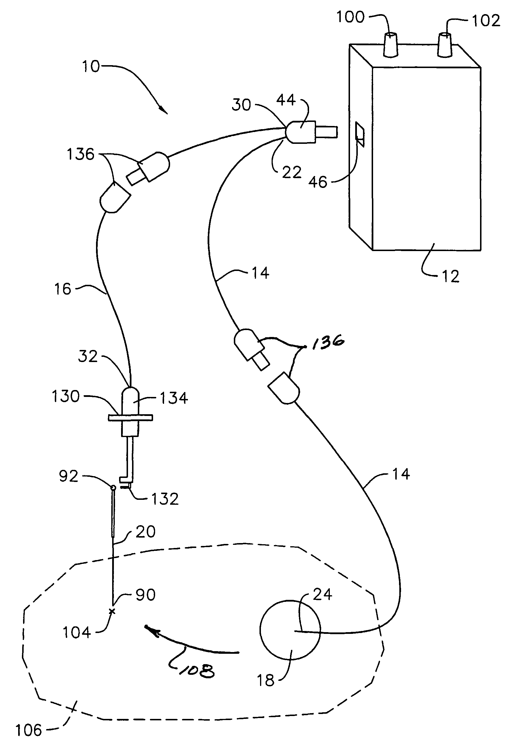
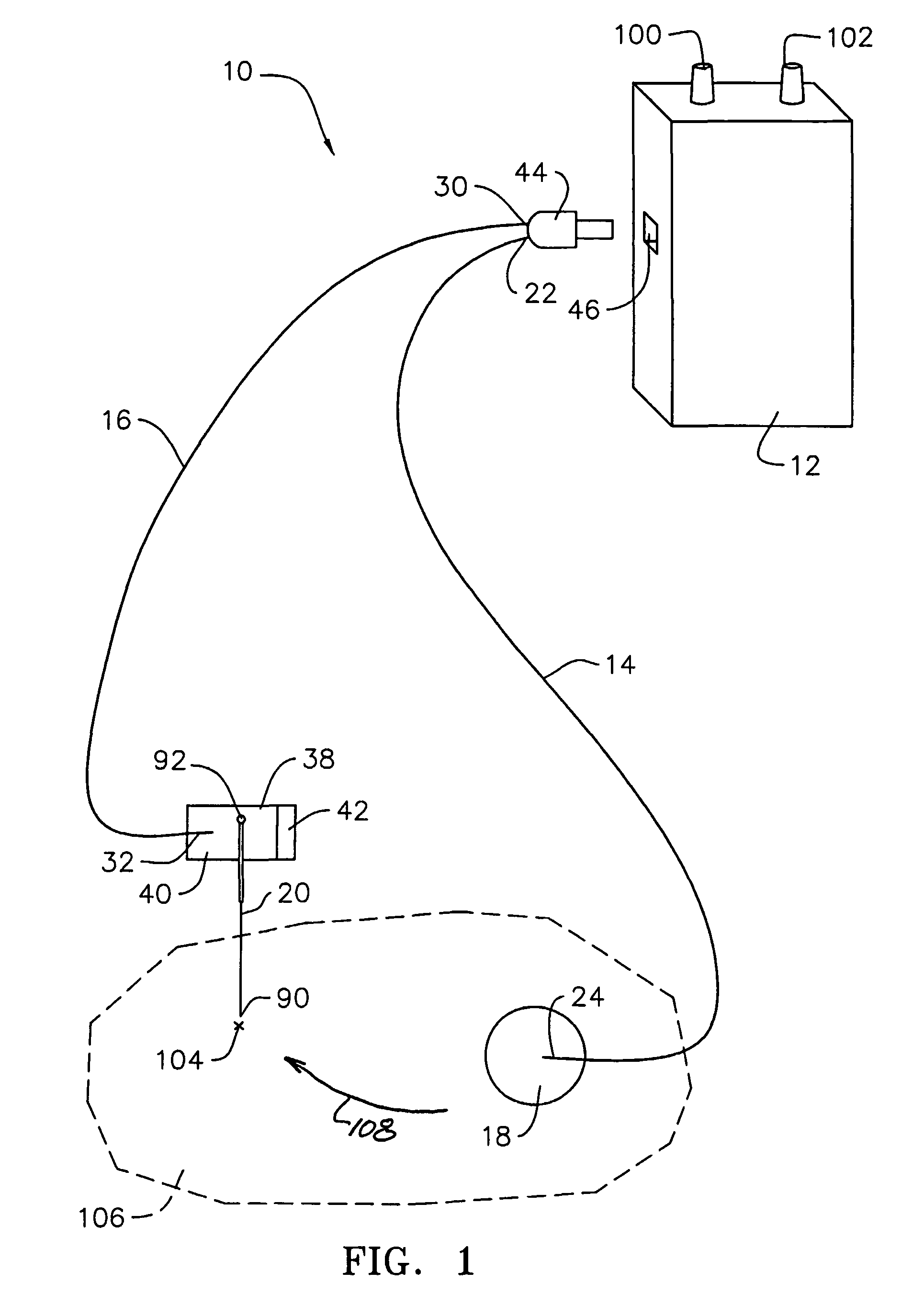
[0023]The electro-nerve stimulation apparatus 10 of the present invention, as illustrated in FIG. 1, comprises a pulse generator 12, a first electrically conductive, insulated lead wire 14, a second electrically conductive, insulated lead wire 16, an electrically conductive transcutaneous electrode 18 and an electrically conductive percutaneous needle electrode 20.

[0024]In the preferred embodiment of the apparatus 10, the first lead wire 14 has a first end 22 and a second end 24. The first end 22 electrically couples to a first lead wire interface of the pulse generator 12. The transcutaneous electrode 18 is preferably fixedly secured to the second end 24 of the first lead wire 14 as described in detail later.

[0025]The second lead wire 16 has a first end 30 and a second end 32. The first end 30 of the second lead wire 16 electrically couples to a second lead wire interface of the pulse generator 12. Fixedly secured to the second end 32 of the second lead wire is an electrically cond...


PUM


Abstract

An electro-nerve stimulation apparatus includes a pulse generator, a first electrically conductive, insulated lead wire, a second electrically conductive, insulated lead wire, an electrically conductive transcutaneous electrode and an electrically conductive percutaneous needle electrode. Connected to one end of the first and second lead wires is a connector for electrically coupling with the pulse generator. The transcutaneous electrode is operably connected to the other end of the first lead wire. An electrically conductive adaptor is secured to the other end of the second lead wire for electrically coupling to the terminal end of the percutaneous needle electrode. The lead wire set includes a single-use mechanism adapted to effectively discourage reuse of the electrodes. In use, the transcutaneous electrode is adhered to the patient's skin distal from the desired internal stimulation site. The percutaneous needle electrode is inserted through the skin in proximity to the desired internal stimulation site. The pulse generator is activated to pass current pulses between the transcutaneous electrode and the percutaneous needle electrode through the internal stimulation site.

Description

BACKGROUND OF THE INVENTION[0001]1. Field of the Invention[0002]The present invention relates generally to electro-nerve stimulation and more particularly to electro-nerve stimulation systems utilizing transcutaneous and percutaneous electrodes.[0003]2. Description of the Related Art[0004]An electro-nerve stimulation system is disclosed in U.S. patent application Ser. No. 09 / 213,558 comprising a pulse generator electrically coupled by lead wires to an electrically conductive transcutaneous electrode (i.e., an electrode which does not penetrate the surface of the skin) and an electrically conductive percutaneous needle electrode (i.e., an electrode which penetrates the surface of the skin). In use, the transcutaneous electrode is positioned distally proximate the stimulation site. The percutaneous electrode needle, is positioned to penetrate the patient's skin and is advanced into proximity with the stimulation site. In this configuration, electrical current pulses from the pulse gen...

Claims


Application Information

Patent Timeline
Patent Type & Authority Patents(United States)
IPC IPC(8): A61N1/00A61NA61N1/04A61N1/05A61N1/18A61N1/36A61N1/375
CPCA61N1/36017A61N1/0551A61N1/3752A61N1/0456
Inventor WILLIAMS, JEFFREY M.VAN AART, FREDVAN DEN BIGGELAAR, HANSVAN LAANEN, LEGAL REPRESENTATIVE, PETRONELLA MARIA COLETAVAN HELVOIRT, PLET
Owner UROPLASTY
Why Eureka
Try Eureka