High impedance bicone antenna

a bicone antenna, high impedance technology, applied in the direction of antennas, antenna details, antenna feed intermediates, etc., can solve the problems of increasing the impedance of the antenna, and the impedance mismatch between the feed line, so as to increase the aperture length, increase the cone diameter, and increase the length

Inactive Publication Date: 2009-05-26
EMS TECHNOLOGIES
View PDF5 Cites 2 Cited by
  • Summary
  • Abstract
  • Description
  • Claims
  • Application Information

AI Technical Summary

Benefits of technology

[0008]The present invention comprises a broadband omni-directional bicone antenna that may have a reduced aperture size, a high input impedance at the central vertex of the cones, and an impedance matching taper to feed the cones.
[0009]The aperture size of a bicone antenna may be reduced by reducing the cone angle. Unfortunately, reducing the cone angle can also result in increasing the impedance of the antenna, thereby creating an impedance mismatch between the feed line connected to the antenna and the antenna itself. Impedance mismatches may cause reflections. In other words, energy intended for the antenna may be reflected back down the feed line to the transmitter or amplifier.
[0011]An aspect of the present invention supports the design of a bicone antenna having a reduced aperture size achieved by reducing the cone angle. As discussed above, this reduction in cone angle can increase the impedance of the cones. An inventive impedance matching mechanism can be used for interfacing to the high impedance characteristic exhibited by the bicone antenna. For example, the impedance matching mechanism can be implemented by a flat conductive taper disposed within the lower cone of the bicone and functioning as an impedance matching transmission line between the external feed line to the antenna and the feed point at the vertex of the cones.
[0013]In yet another aspect of the present invention, the geometry of the cones may be modified to support an end section of one or both of the cones where the end segment is substantially cylindrical. Such a geometry can support an increase in aperture length without increasing cone diameter. The increase in length can support lower frequency operation.

Problems solved by technology

Unfortunately, reducing the cone angle can also result in increasing the impedance of the antenna, thereby creating an impedance mismatch between the feed line connected to the antenna and the antenna itself.
Impedance mismatches may cause reflections.

Method used


Image

  • High impedance bicone antenna
  • High impedance bicone antenna
  • High impedance bicone antenna

Examples


Embodiment Construction

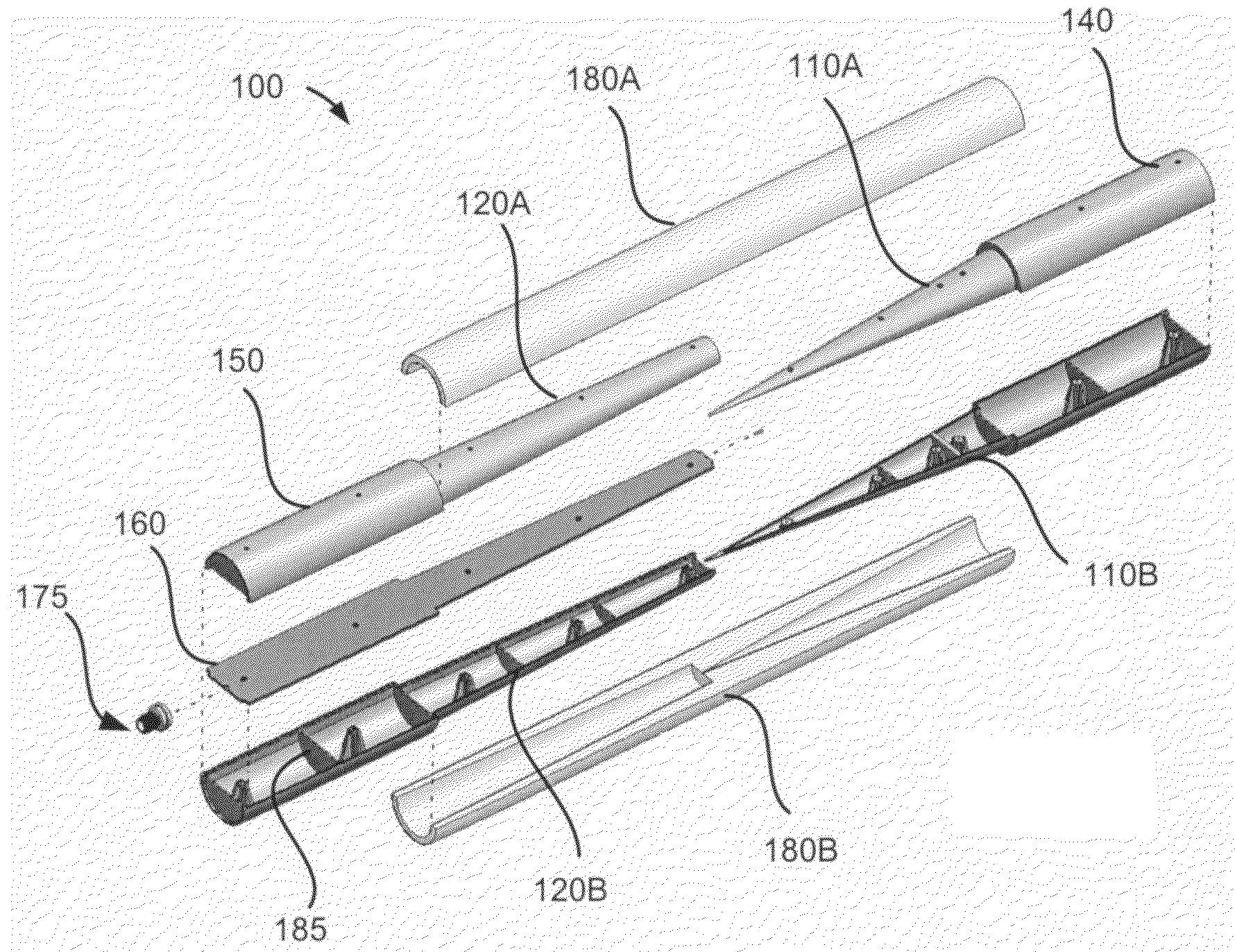
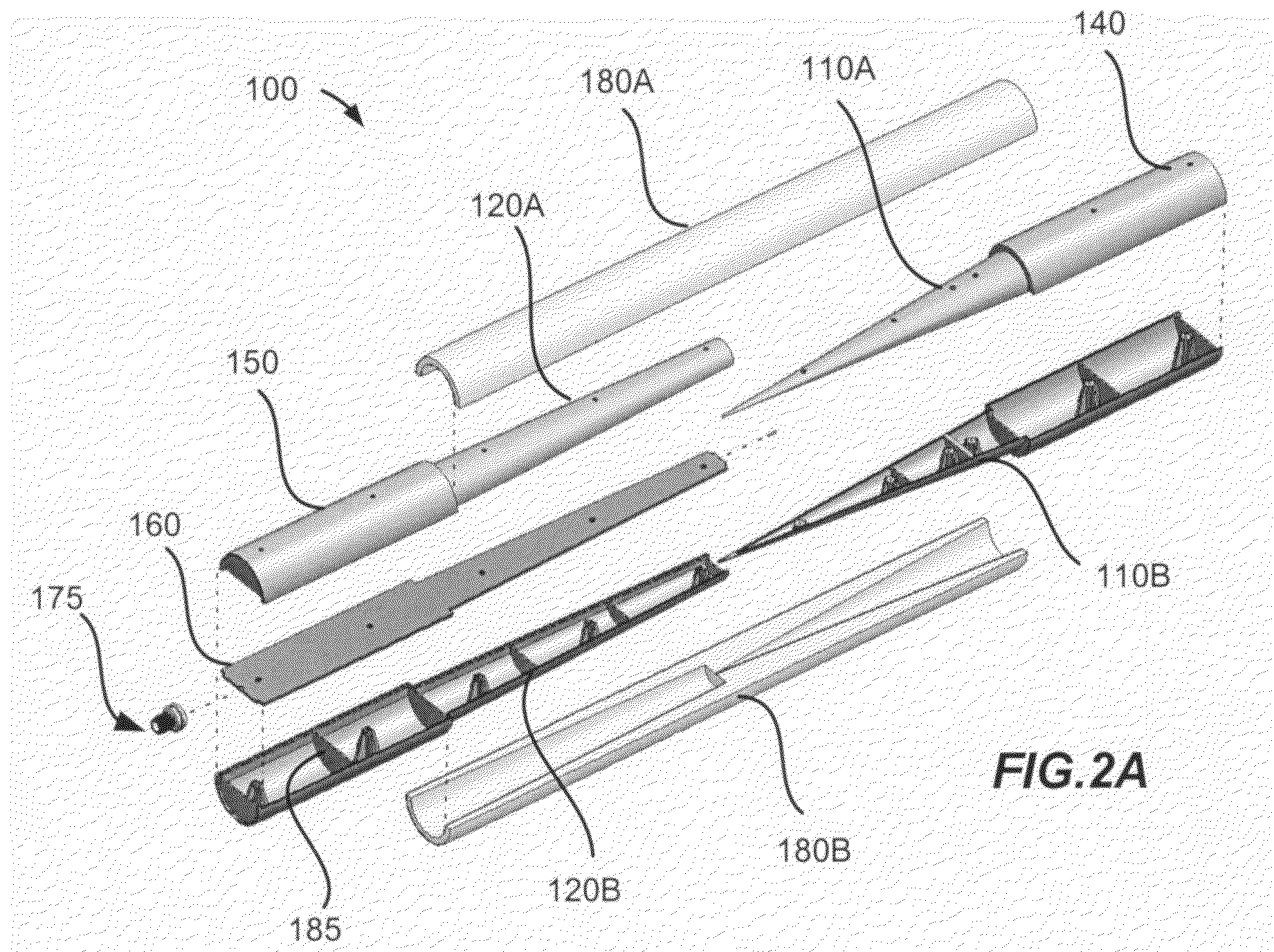
[0020]The present invention supports the design and operation of a bicone antenna having a reduced aperture size achieved by reducing the cone angle. This reduction in cone angle can increase the impedance of the cones thus providing a high impedance bicone antenna system. In recognition of this high impedance characteristic, an inventive impedance matching mechanism can be used to interface with the bicone antenna system. An exemplary impedance matching mechanism is implemented by a flat conductive taper disposed within a cone of the bicone antenna system. This flat conductive taper functions as an impedance matching transmission line between the external feed line to the antenna and the feed point at the vertex of the cones. The single conductive taper, useful for impedance matching, can function as the center conductor of a coaxial feed mechanism. The inside of the bottom cone can serve as the outside conductor (or shielding conductor, or return) of the tapered feed line.

[0021]Th...


PUM


Abstract

A high impedance bicone antenna system supporting ultra wideband operation. The antenna may comprise a reduced aperture size and reduced half-angles of the conductive cones forming the antenna. Reduction in cone angles may increase the impedance of the cones. An impedance matching mechanism for interfacing to the high impedance bicone may be positioned within one of the cones by a dielectric material. The impedance matching mechanism may be a flat conductive taper functioning as an impedance matching transmission line between an external feed line and the antenna. The conductive taper may function as a center conductor of a coaxial feed mechanism where the inside of the cone around the taper serves as the outside conductor, or return, of the tapered feed. The geometry of the cones may be modified to provide one or more end segments that are substantially cylindrical.

Description

RELATED APPLICATION[0001]This patent application claims priority under 35 U.S.C. §119 to U.S. Provisional Patent Application No. 60 / 772,233, entitled “High Impedance Bicone,” filed Feb. 10, 2006. The complete disclosure of the above-identified priority application is hereby fully incorporated herein by reference.FIELD OF THE INVENTION[0002]The present invention relates to an omni-directional bicone antenna and more specifically to a high impedance bicone antenna with a reduced aperture size and a tapered impedance matching feed.BACKGROUND[0003]A bicone is generally an antenna having two conical conductors, where the conical elements share a common axis, and a common vertex. The conical conductors extend in opposite directions. That is, the two flat portions of the cones face outward from one another. The flat portion of the cone can also be thought of as the base of the cone or the opening of the cone. The flat portion, or opening, of a cone is at the opposite end of the cone from t...

Claims


Application Information

Patent Timeline
Patent Type & Authority Patents(United States)
IPC IPC(8): H01Q13/00
CPCH01Q9/28H01Q13/04
Inventor BLACK, DONALD N.VOSS, JOHN D.NEWBURY, TERENCE D.
Owner EMS TECHNOLOGIES
Why Eureka
Try Eureka