Multiple-element antenna array for communication network

a communication network and antenna array technology, applied in the field of radio frequency (rf) communications, can solve the problems of increasing the number of rf feed cables per base station, affecting the quality of service, so as to achieve the effect of reducing the asymmetry of signal patterns

Active Publication Date: 2009-05-26
ALCATEL-LUCENT USA INC
View PDF11 Cites 30 Cited by
  • Summary
  • Abstract
  • Description
  • Claims
  • Application Information

AI Technical Summary

Benefits of technology

[0008]Collectively, the antennas have at least six ports, e.g., two each for the dual-polarized antennas and one active port for each of the single-polarized antennas. In another embodiment, a duplexer unit is connected to one or more of the antennas. (By “duplexer unit” it is meant one or more duplexer circuits, which may be housed together or separately.) The duplexer unit reduces the number of RF feed cable outlets of the antenna array from six to four, enabling the antenna array to be connected to a base station unit (e.g., base station controller or other electronics) by way of four RF feed cables. If the system includes more than four antennas in the first group, the duplexer unit may be used to reduce the number of feed cable outlets to no more than the number of antennas in the first group.
[0010]In another embodiment, the four antennas are linearly arranged. The two center antennas are dual-polarized antennas for both transmission and diversity reception. The outer two antennas are configured for single-polarized use in beamforming transmissions. Thus, the outer antennas may be either single-polarized antennas (e.g., an antenna column having an array of radiating elements each oriented at a selected polarization), or dual-polarized antennas where one of the arrays of radiating elements is terminated. This might be useful for mitigating signal pattern asymmetry.
[0011]In another embodiment, at least one of the antennas in the second group is spaced apart from the first group and the other antennas in the second group, by a distance adapted for spatial diversity reception of signals over the reverse link. In other words, the second group includes one or more antennas co-extensive with the first group, and one or more additional antennas spaced apart by a distance suitable for spatial diversity reception. The distance is chosen based on the environment in which the antenna system is used, for achieving acceptable diversity reception performance.

Problems solved by technology

However, supporting the need for increased capacity can negatively affect quality of service, particularly if no special attempt is made to address this need.
For example, signal distortion resulting from co-channel interference may increase as channel load increases.
To explain further, in modern wireless systems one of the most severe limitations imposed on adaptive antenna arrays is the number of RF feed cables per base station.
Each of the three array configurations has certain disadvantages in suburban or light urban environments.
Over the forward link, a combination of beamforming and transmission diversity is used, however, which may result in gain values lower than in a 4-column, single polarization array as other forms of diversity exist in modern cellular systems.

Method used


Image

  • Multiple-element antenna array for communication network
  • Multiple-element antenna array for communication network
  • Multiple-element antenna array for communication network

Examples


Embodiment Construction

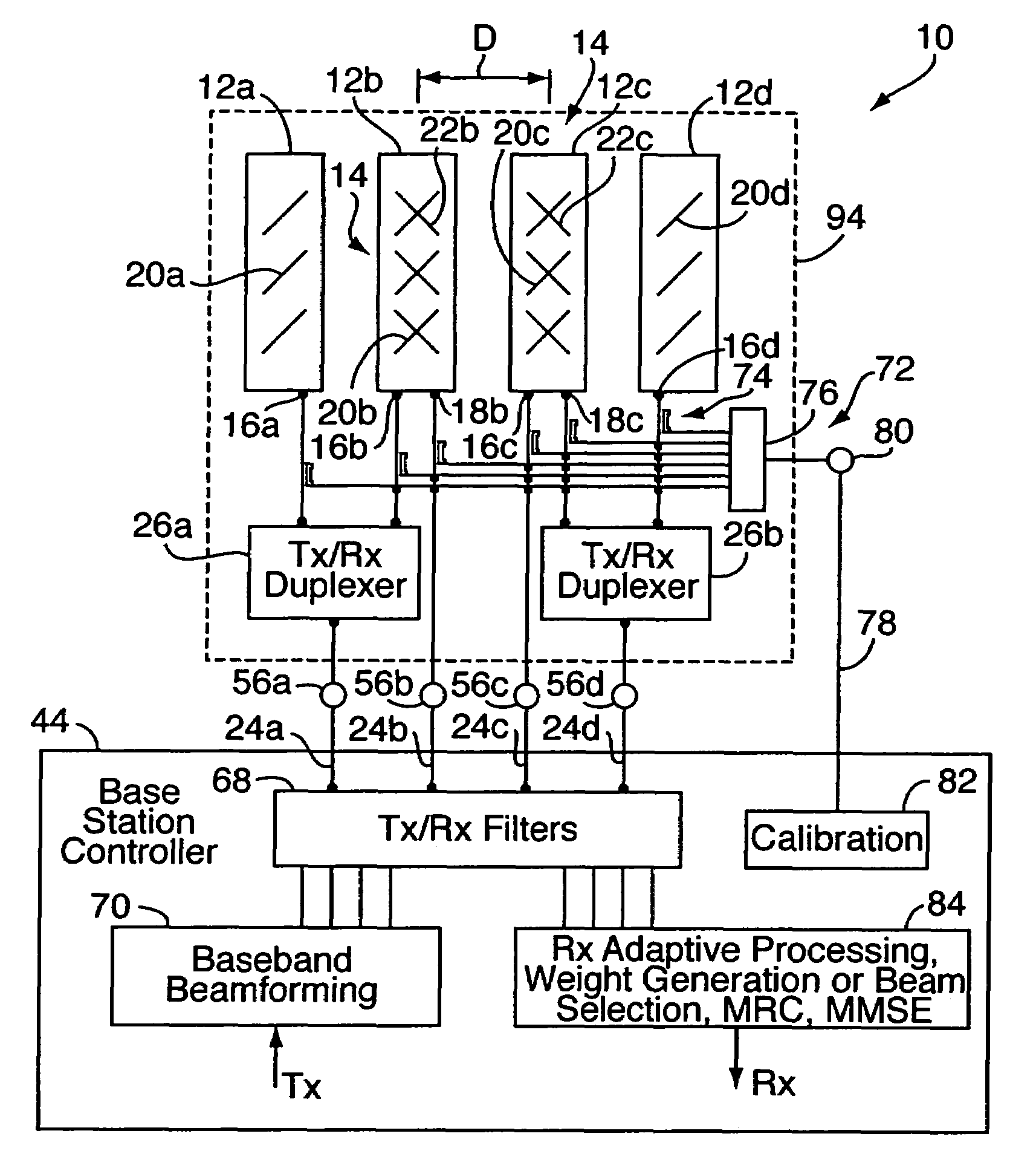
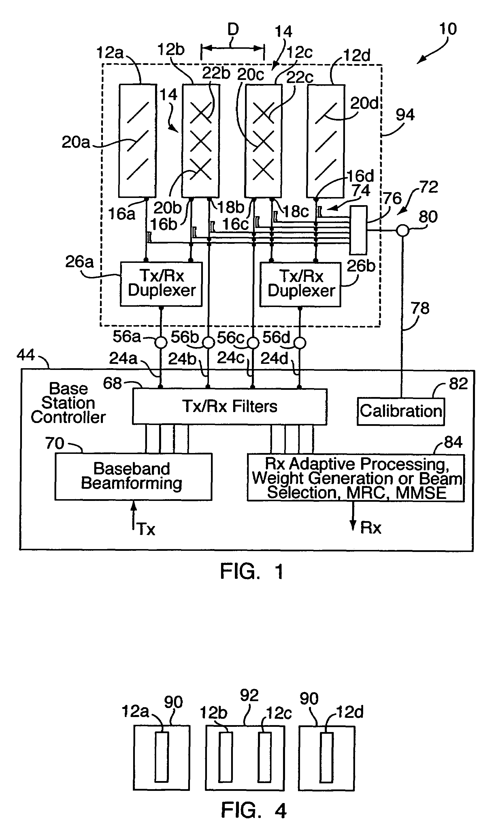
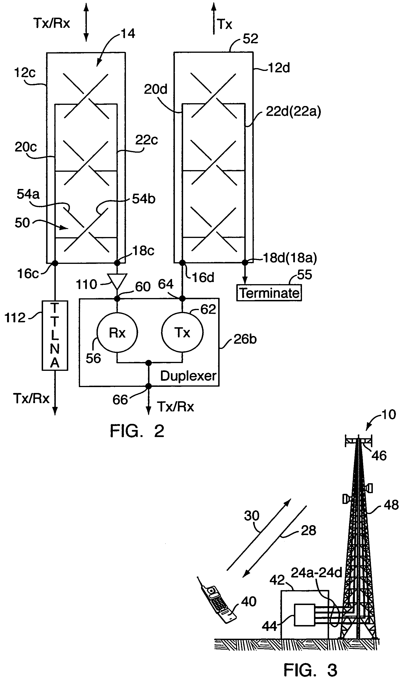
[0018]With reference to FIGS. 1-4, an embodiment of the present invention relates to an antenna array system 10 for transmitting and receiving radio-frequency (RF) signals in a wireless communication network. The system 10 includes four linearly arranged, spaced-apart antennas 12a-12d. The antennas may be antenna columns. Two or more of the columns 12b, 12c may be dual-polarized antenna columns. Each dual-polarized antenna column 12b, 12c is a vertical linear array 14 of dual-polarized radiating elements or groups of elements (sub-arrays) having two independent ports 16b, 18b or 16c, 18c. In other words antenna column 12b includes a first array 20b of radiating elements oriented at a first polarization and connected to a first port 18b, and a second array 22b of radiating elements oriented at a second polarization and connected to a second port 16b. (Note that ports 16b, 18b are shown “reversed”—port 18b is connected to array 20b, for both transmission and reception of signals, whil...


PUM


Abstract

An antenna array includes four closely spaced, linearly arranged antenna columns. At least two of the columns, e.g., the center two columns, are dual-polarized. Spacing between neighboring columns is about ½λ, where λ is the free space wavelength at the network carrier frequency. Each column includes a first vertical linear array of radiating elements or groups of elements (sub-arrays) connected to a port. The dual-polarized columns each further include a second linear array of radiating elements oriented at a different polarization than the first array. (For example, horizontal / vertical or slant 45°.) Array ports are connected with four RF feed cables using duplexers in such a way so as to provide two different antenna configurations for forward link and reverse link frequencies, namely, a four-column closely spaced beam-forming array at the forward link and a two-column dual-polarized array at the reverse link for 4-branch diversity reception.

Description

FIELD OF THE INVENTION[0001]The present invention relates to radio-frequency (RF) communications and, more particularly, to radio wave antennas.BACKGROUND OF THE INVENTION[0002]Various advances in commercial wireless and networking technologies have enabled the support of voice and high-speed data services to wireless unit end users, e.g., those using mobile phones, wireless personal digital assistants (PDA's), or the like. As third generation wireless packet data networks have evolved to support a wide range of multimedia and other high-speed data services, packet data voice services have become a viable alternative or replacement for traditional circuit switched voice communications. Because of the increased demand for wireless communications generally, and especially in terms of high-speed data transfer, service providers have sought to increase network capacity. However, supporting the need for increased capacity can negatively affect quality of service, particularly if no speci...

Claims


Application Information

Patent Timeline
Patent Type & Authority Patents(United States)
IPC IPC(8): H01Q21/00
CPCH01Q1/246H01Q3/267H01Q21/08H01Q21/24
Inventor KORISCH, ILYA ALEXANDERSONI, ROBERT ATMARAMWU, KAM H.
Owner ALCATEL-LUCENT USA INC
Why Eureka
Try Eureka