OFDM channel estimation and tracking for multiple transmit antennas

a channel estimation and multiple transmit antenna technology, applied in multiplex communication, multi-frequency code system details, etc., can solve the problems of channel estimation and tracking, channel estimation and tracking remain an issue, and ofdm modulation encounters problems at high doppler spread

Active Publication Date: 2009-05-26
MOTOROLA SOLUTIONS INC
View PDF5 Cites 33 Cited by
  • Summary
  • Abstract
  • Description
  • Claims
  • Application Information

AI Technical Summary

Problems solved by technology

Also, in the context of wireless local area networks (‘WLANs’), current data rates (54 Mbps on top of the physical layer) are foreseen to be insufficient for very dense urban deployment, such as for hot spot coverage.
However channel estimation and tracking remains an issue, especially in the presence of high mobility or high frequency and data rates.
Like other digital communication systems, OFDM modulation encounters problems at high Doppler spreads, which occur notably when the user is moving fast, for example in a car, or even at pedestrian speeds when investigating the area of higher frequency bands where more spectrum is available such as the 60 GHz band.

Method used


Image

  • OFDM channel estimation and tracking for multiple transmit antennas
  • OFDM channel estimation and tracking for multiple transmit antennas
  • OFDM channel estimation and tracking for multiple transmit antennas

Examples


first embodiment

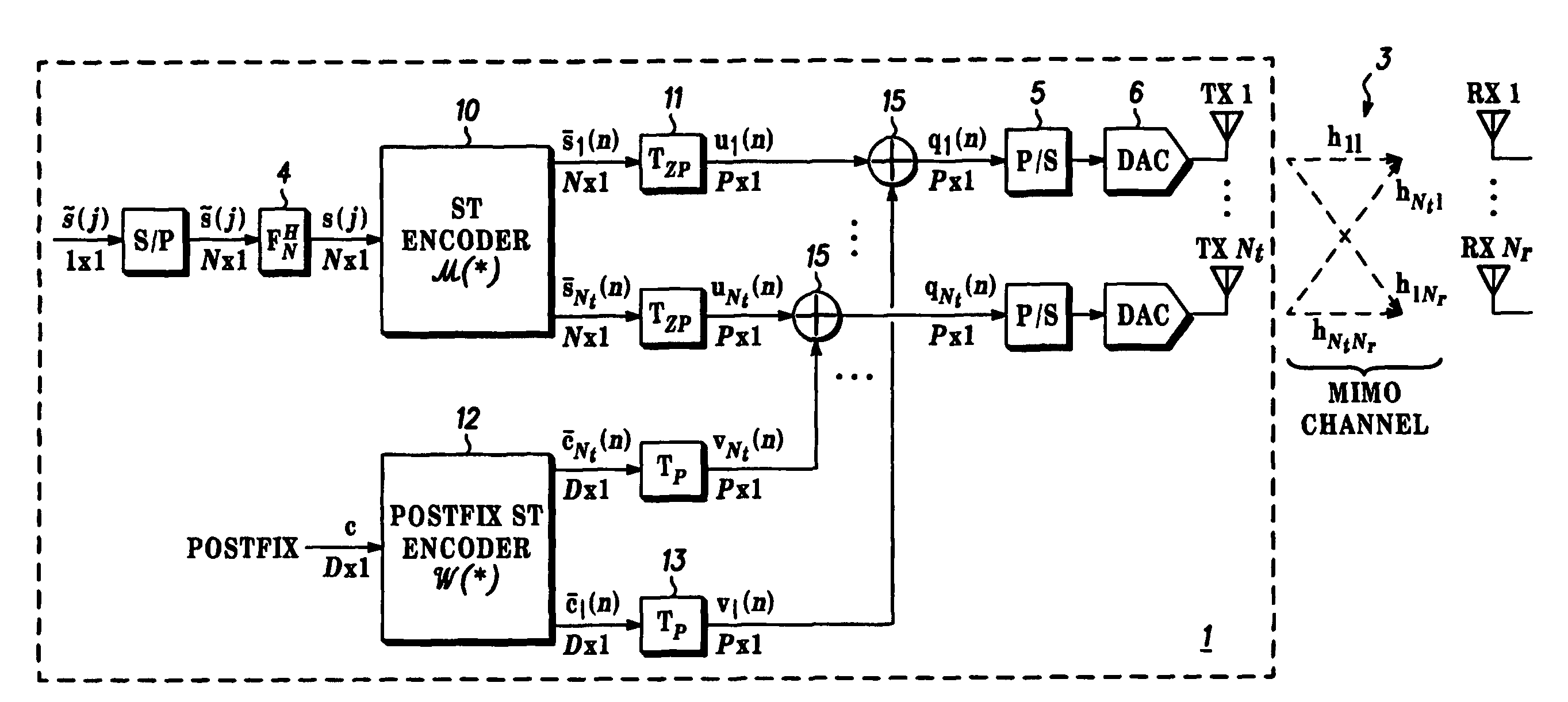
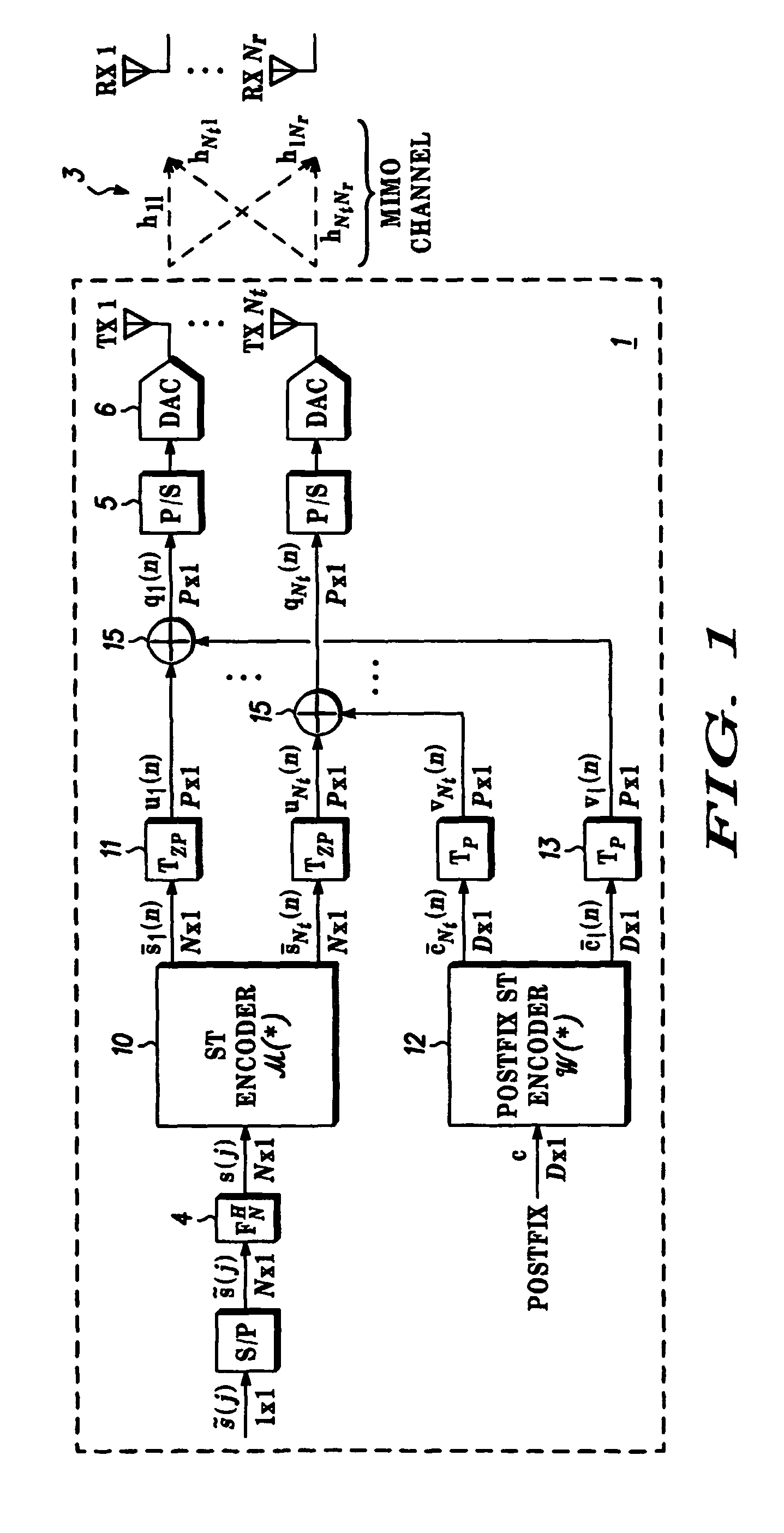
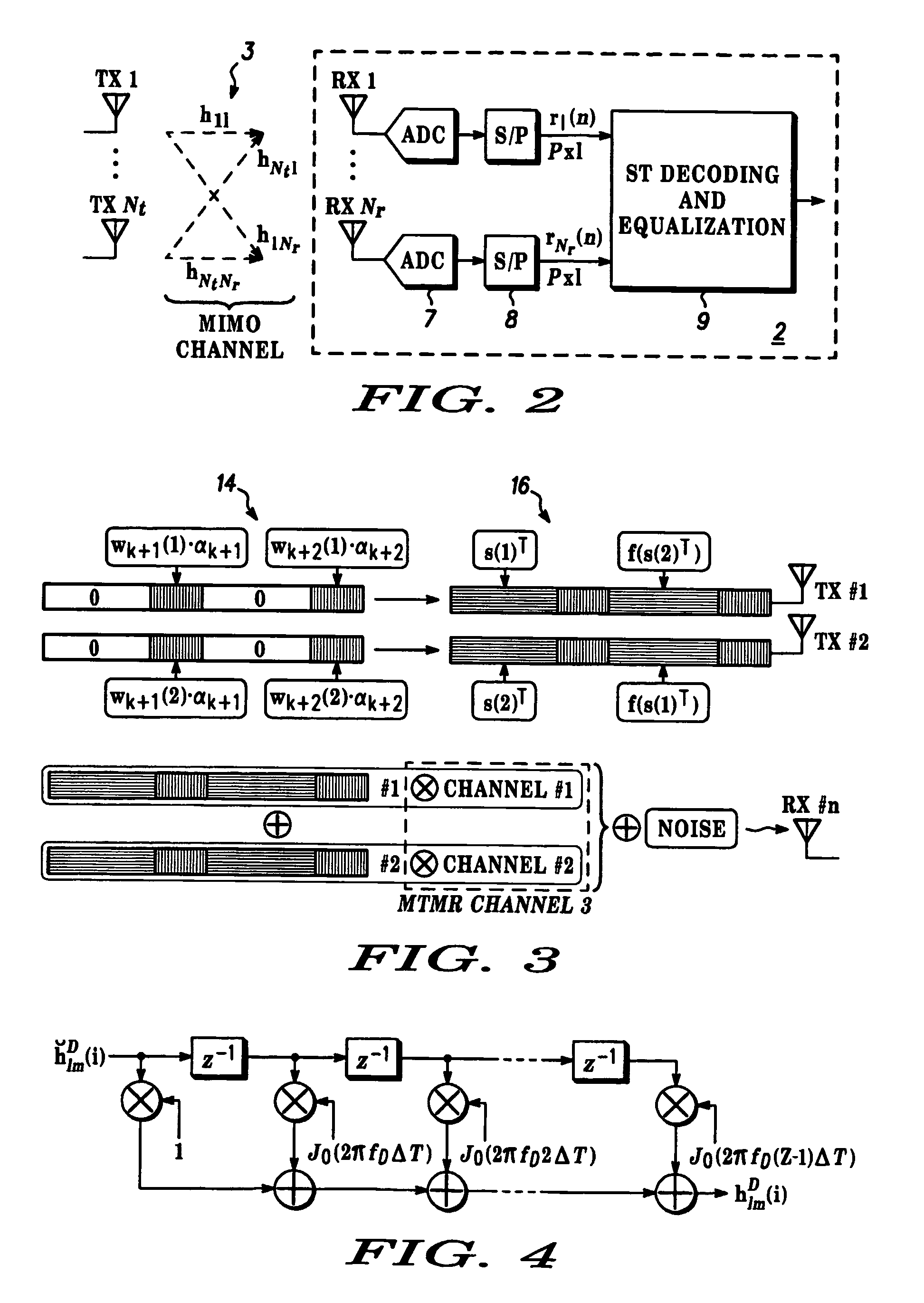
[0058]STBC is based on ZP-OFDM decoding. The system includes modulators using pseudo-random postfixes at the transmitter and also equalizer structures derived for the MTMR case from those described for the Single Transmit Single Receive (STSR) case in our co-pending European Patent Application EP 02 292 730.5 based on the transformation of the received PRP-OFDM vector to the ZP-OFDM case. The system is described for the case of Nt=2 transit and Nr=1 receive antennas, although it will be appreciated that the system is applicable to other numbers of antennas. The ST encoder operates over Nt×M vectors with Nt=M=2. Since Nr=1, the subscript 1≦m≦Nr is not used in the following analysis. Perfect knowledge of the channels hl, I≦l≦Nt is assumed but it will be appreciated that the system is capable of working with imperfect channel knowledge.

[0059]At the transmitter, a 2×1 ZP-ST encoder  is used, which takes two consecutive OFDM symbols s(2i) and s(2i+1) to form the following coded matrix:

[0...

second embodiment

[0066]STBC system is based on equalization of the full received block by diagonalisation of pseudo-circulant channel matrices. The ST data encoder  used in the demodulator and equaliser 9 is based on a version of the single antenna system described in our co-pending European Patent Application EP 02 292 730.5 modified to enable the equalization structure that is detailed below and outputs blocks Nt×M vectors with Nt=M=2.  and  are specified such that they generate the following matrix Q(i)={ql(2i+k), 1≦l≦2, 0≦k<2} at the antenna outputs:

[0067]Q⁡(i)=[[s⁡(2⁢i)α⁡(2⁢i)⁢c]-PP0⁢Qβ⁡(i)⁡[s*⁡(2⁢i+1)α⁡(2⁢i+1)⁢c*][s⁡(2⁢i+1)α⁡(2⁢i)⁢c]PP0⁢Qβ⁡(i)⁡[s*⁡(2⁢i)α⁡(2⁢i+1)⁢c*]]Equation⁢⁢14

PP0 being a permutation matrix defined as previously (inversing the order of the vector elements), α(i) is complex with |α(i)|=1 being pseudo-random complex weighting factors as defined in our co-pending European Patent Application for the single antenna case with α(2i+1)=β2(i)α(2i), and β(i)−α(2i=2) / α(2i). Qβ(i) is def...


PUM


Abstract

Multiple Transmit Multiple Receive Orthogonal Frequency Division Multiplexing (‘OFDM’) comprising generating bit streams and corresponding sets of N frequency domain carrier amplitudes ({tilde over (s)}(kN+j), 0≦j≦N−1) modulated as OFDM symbols subsequently to be transmitted from a transmitter, where k is the OFDM symbol number and j indicates the corresponding OFDM carrier number. Affix information is inserted at the transmitter into guard intervals between consecutive time domain OFDM symbols and are used at the receiver to estimate the Channel Impulse Response (Hlm) of the transmission channels, the estimated Channel Impulse Response (Ĥlm) being used to demodulate the bit streams in the signals received at the receiver. The affix information is known to the receiver, as well as to the transmitter, and is mathematically equivalent to a vector (cD) that is common to the time domain OFDM symbols multiplied by at least first weighting factors (αk) that are different for one time domain OFDM symbol (k) than for another and second weighting factors (wi(k)) that enable one of the transmit antenna means (i) to be distinguished from another.

Description

FIELD OF THE INVENTION[0001]This invention relates to communication using Orthogonal Frequency Division Multiplexing (‘OFDM’) and, more particularly, to channel estimation and tracking in OFDM communication.BACKGROUND OF THE INVENTION[0002]This invention relates to communication using Orthogonal Frequency Division Multiplexing (‘OFDM’) and, more particularly, to channel estimation and tracking in OFDM communication.BACKGROUND OF THE INVENTION[0003]OFDM communication has been chosen for most of the modern high-data rate communication systems (Digital Audio Broadcast—DAB, Terrestrial Digital Video Broadcast—DVB-T, and Broadband Radio Access Networks—BRAN such as HIPERLAN / 2, IEEE802.11a / g, IEEE802.15.3a, for example, and is considered for future wide-band telephony standards, referred to as “4G”). However, in most cases the receiver needs an accurate estimate of the channel impulse response. Also, in the context of wireless local area networks (‘WLANs’), current data rates (54 Mbps on ...

Claims


Application Information

Patent Timeline
Patent Type & Authority Patents(United States)
IPC IPC(8): H04B7/02H04L1/02H04B7/04H04J99/00H04L1/06H04L25/02H04L27/26
CPCH04B7/04H04L1/0618H04L25/023H04L27/2605H04L27/2647
Inventor DIAS, ALEXANDRE RIBEIRODE COURVILLE, MARC BERNARDMUCK, MARKUS D.
Owner MOTOROLA SOLUTIONS INC
Why Eureka
Try Eureka