Vacuum sealer

a vacuum sealer and sealer technology, applied in the field of vacuum sealers, can solve the problems of reducing the durability of the product, not being installed or detached, and affecting the use of weak users, and achieve the effect of simplifying the construction of the vacuum sealer

Inactive Publication Date: 2009-06-02
SUNG YI JE
View PDF11 Cites 40 Cited by
  • Summary
  • Abstract
  • Description
  • Claims
  • Application Information

AI Technical Summary

Benefits of technology

[0011]Accordingly, the present invention has been made keeping in mind the above problems occurring in the prior art, and an object of the present invention is to provide a vacuum sealer, in which a packing member provided on a lower body has a linear shape, thus simplifying the construction of the vacuum sealer.

Problems solved by technology

However, the detachable vacuum space creating member of the conventional vacuum sealer, disclosed in Patent Laid-Open Publication No. 2005-0107107, is not installed or detached in a fixed direction.
Because of this repeated detachment and attachment, a gap may form at the coupling site, and leakage may occur at an exhaust passage coupled to a vacuum pump, thus resulting in reduced durability of the product.
Therefore, when the vacuum sealer is used at first, the hook and the latch are stiff, so that it is difficult for weak users to use the vacuum sealer.
Further, after the vacuum sealer has been used for a lengthy period of time, the hook and the latch may wear out or break.
However, when the space is narrow, the space cannot support products contained in the vacuum bag, so that a vacuum packing operation cannot be performed smoothly.

Method used


Image

  • Vacuum sealer
  • Vacuum sealer
  • Vacuum sealer

Examples


Embodiment Construction

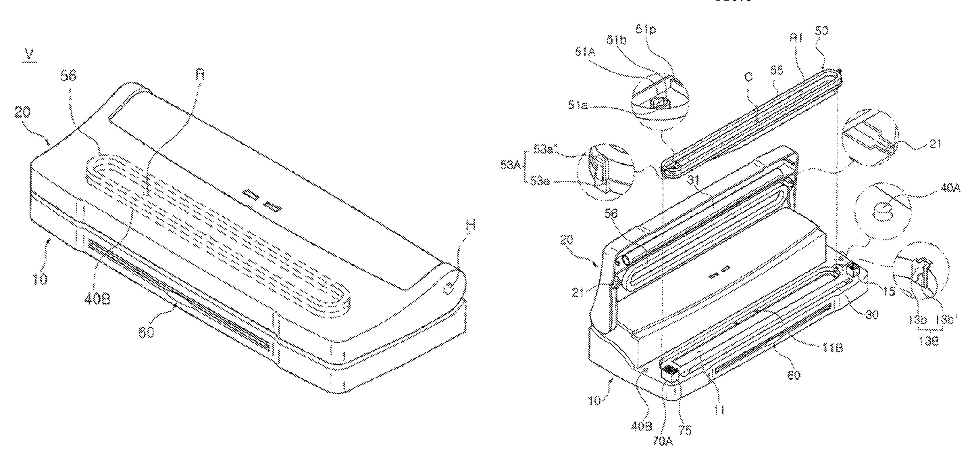
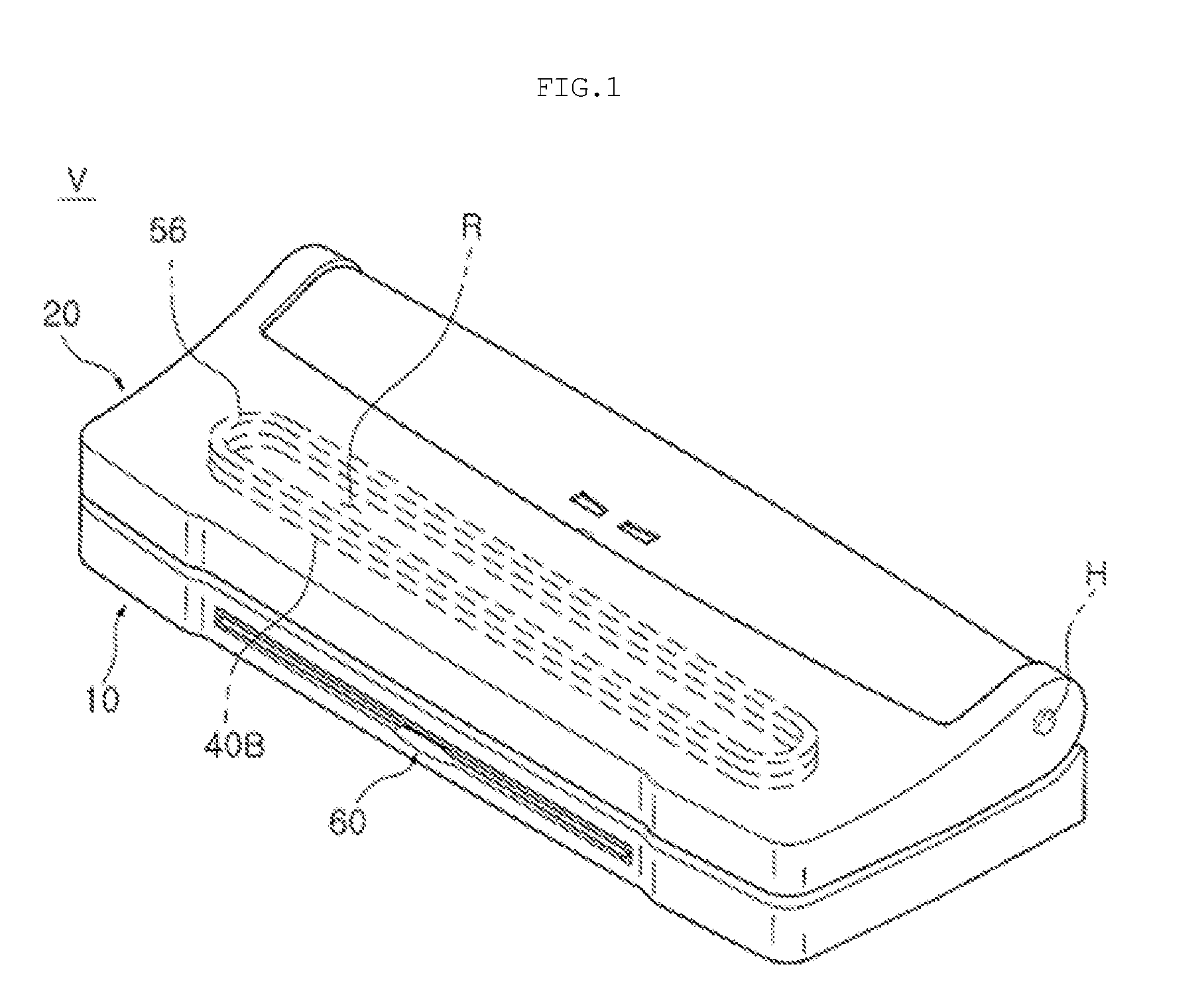
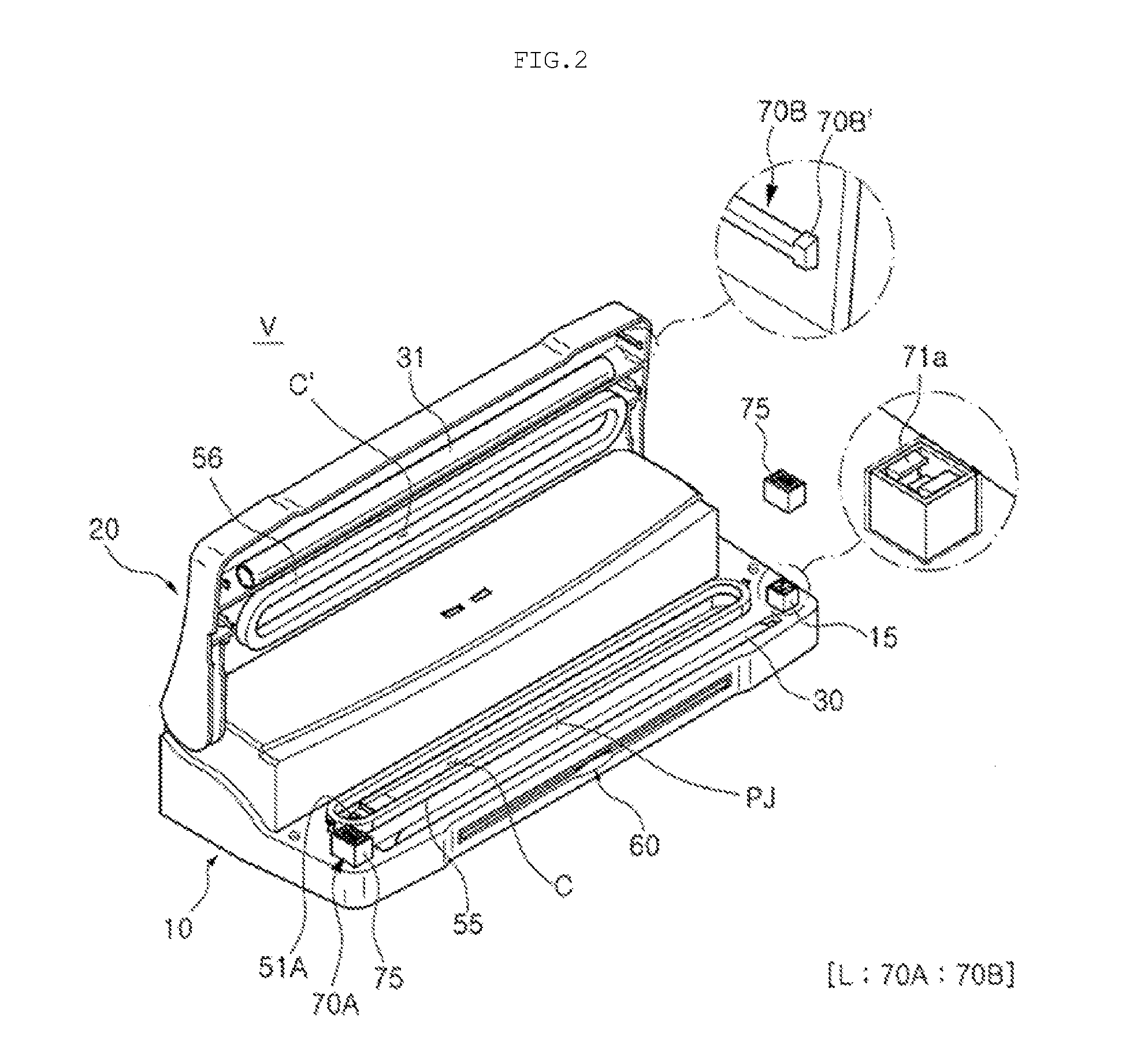
[0047]The present invention will be described below in detail with reference to the accompanying drawings. The same reference numerals throughout the drawings, that is, the same reference numerals in a second digit and a first digit, or in a second digit, a first digit, and an alphabet character, denote elements having the same function. If there is no special mention, the elements denoted by the reference numerals are to be taken as elements complying with the above-mentioned reference scheme. The orientation of the vacuum sealer V according to the present invention is specified with reference to FIGS. 1 and 2. That is, the position of an element 10 which is located at a lower position when seen from the direction in which gravity acts, and holds important parts, such as a heater 30 and a pump 40 (see, FIG. 11) is set as a lower position, and the element 10 is designated as a ‘lower body’. The position opposite the position of the lower body is set as an upper position, and an elem...


PUM


Abstract

Disclosed herein is a vacuum sealer, which exhausts air from a thermal adhesive vacuum bag containing products and then heats and seals the open end of the vacuum bag. The vacuum sealer includes a lower body. An upper body is pivotably mounted to the lower body in such a way as to engage with the lower body. A heater is installed in either or both the lower body or / and the upper body, and heats and seals a vacuum bag. A vacuum space creating member is installed in either or both the lower body or / and the upper body, and isolates an end of the vacuum bag which is evacuated from an exterior, thus creating a vacuum space. A vacuum pump is coupled via a tube to an exhaust hole communicating with the vacuum space created by the vacuum space creating member.

Description

BACKGROUND OF THE INVENTION[0001]1. Field of the Invention[0002]The present invention relates generally to a vacuum sealer, which exhausts air from a thermal adhesive vacuum bag containing products such as foodstuffs, and then heats and seals the open end of the vacuum bag, and, more particularly, to a vacuum sealer, which uses a linear packing member, in place of a closed-loop shaped packing member, used in a conventional vacuum sealer, thus simplifying the construction of a body accommodating a vacuum pump, in addition to maintaining the same vacuum level as a conventional vacuum sealer, and which includes a detachable vacuum space creating member at which the end of the vacuum bag is located and to which vacuum pressure is applied using a pump, a vacuum release means which supplies external air into a vacuum space so as to release the vacuum after air has been exhausted from the vacuum bag and the end of the vacuum bag is heated and sealed, and a filtering means which prevents im...

Claims


Application Information

Patent Timeline
Patent Type & Authority Patents(United States)
IPC IPC(8): B65B31/04
CPCB65B31/046B65B31/047
Inventor SUNG, YI-JESHIN, JOON-CHEL
Owner SUNG YI JE
Why Eureka
Try Eureka