
Compressor valve

a compression valve and valve plate technology, applied in the direction of functional valve types, machines/engines, positive displacement liquid engines, etc., can solve the problem of soft stop of the valve plate, and achieve the effect of short travel

Active Publication Date: 2009-06-02
WALTER J TUYMER & ANNELIESE TUYMER CO TRUSTEES OF THE TUYMER FAMILY TRUST
View PDF6 Cites 7 Cited by
  • Summary
  • Abstract
  • Description
  • Claims
  • Application Information

AI Technical Summary

Benefits of technology

The solution provides a more efficient and durable dampening system that reduces the impact velocity of the valve plate, prolonging its life and preventing damage by ensuring a controlled and soft stop, even when the valve plate does not move parallel to the valve seat.

Problems solved by technology

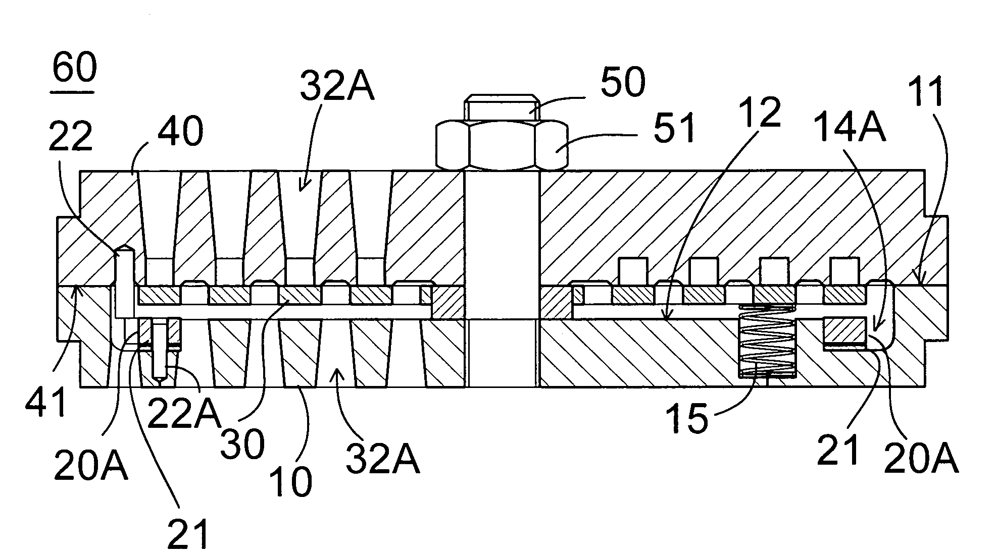
The spring allows the dampening ring to travel a small fraction of the valve plate lift, thereby causing a soft stop of the valve plate.

Method used


Image

  • Compressor valve
  • Compressor valve
  • Compressor valve

Examples


Embodiment Construction

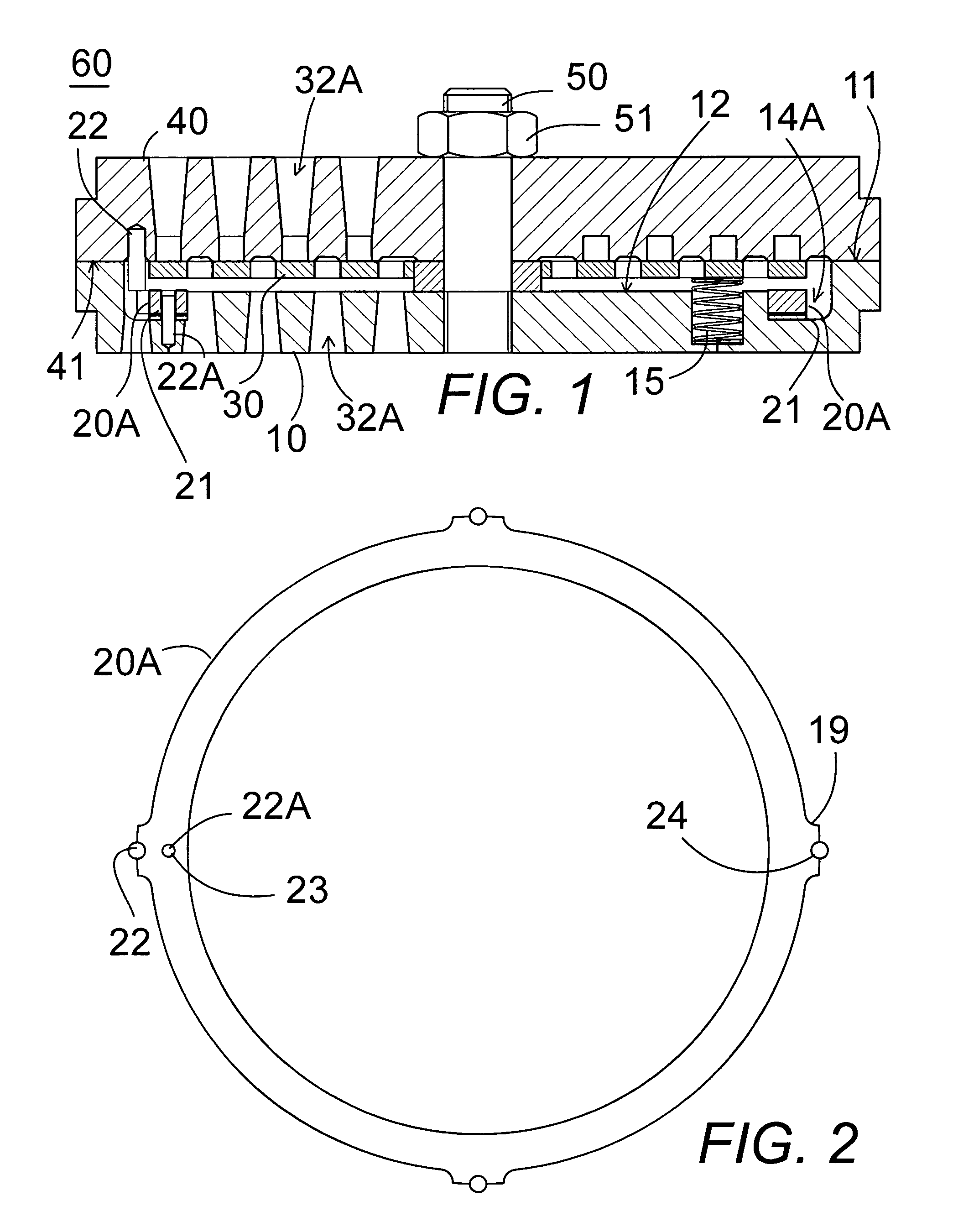
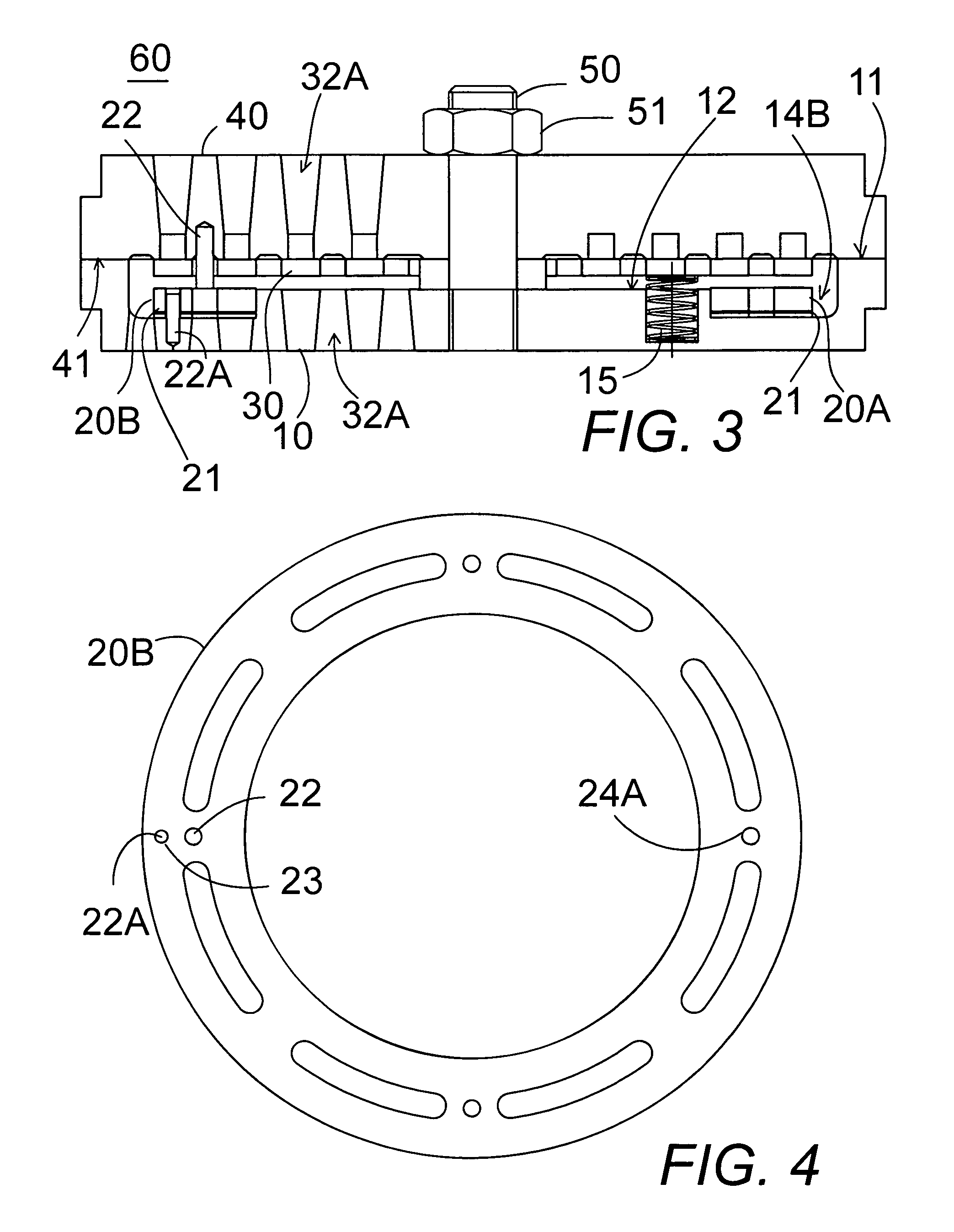
[0040]In FIGS. 1-6, a plate-type compressor valve assembly device 60 comprises a valve seat 40, a valve stop plate or valve guard 10, a shaft 50 with a nut 51, a ported valve plate 30, preferably made of non-metallic material, such as synthetic material, including plastic, and a dampening ring 20A and 20B with a spring 21, preferably a wafer spring.

[0041]The compressor valve comprises a flat cylindrical valve seat 40 having at least one flat face 41 and a parallel flat cylindrical valve stop plate 10 having a peripheral flat surface 11 to mate with a peripheral portion of the flat face 41 of the valve seat and a recessed flat surface 12 spaced apart from the flat face 41 of the valve seat forming an interior plate receiving area therebetween. The stop plate 10 has an annular ring receiving groove 14A, 14B further recessed below the recessed flat surface 12 of the valve stop plate between the recessed flat surface 12 and the peripheral flat surface 11. The valve seat 40 and the valve...


PUM


Abstract

A steel dampening ring rests on a wafer spring in an annular groove in a compressor valve stop plate to dampen the action of the plastic valve plate to prolong the life of the valve.

Description

CROSS-REFERENCE TO RELATED APPLICATIONS[0001]Not Applicable.STATEMENT REGARDING FEDERALLY SPONSORED RESEARCH OR DEVELOPMENT[0002]Not Applicable.THE NAMES OF THE PARTIES TO A JOINT RESEARCH OR DEVELOPMENT[0003]Not Applicable.BACKGROUND OF THE INVENTION[0004]1. Field of the Invention[0005]The present invention relates to compressor valves and particularly to a compressor valve with a light weight synthetic valve plate having a single spring loaded steel ring dampening system.[0006]2. Description of Related Art Including Information Disclosed Under 37 CFR 1.97 and 1.98[0007]A good compressor valve has to be efficient and last long. The efficiency is simply a function of the area the valve provides when it is open since the valve is practically an orifice, causing a pressure drop across it which means loss of horsepower. Valve life is achieved by limiting the impact of the valve plate when it opens as well as when it closes. The opening impact can be controlled by limiting the valve lif...

Claims


Application Information

Patent Timeline
Patent Type & Authority Patents(United States)
IPC IPC(8): F16K15/08
CPCF04B39/1053F16K15/08Y10T137/7839Y10T137/7864Y10T137/785Y10T137/7865
Inventor TUYMER, WALTER
Owner WALTER J TUYMER & ANNELIESE TUYMER CO TRUSTEES OF THE TUYMER FAMILY TRUST
Learn More