Exhaust system for motorcycle

a technology for exhaust systems and motorcycles, applied in the direction of machines/engines, cycles, transportation and packaging, etc., can solve the problems of difficult to ensure the minimum ground clearance or the banking angle of the vehicle, and achieve the effect of ensuring the capacity of the muffler

Inactive Publication Date: 2009-06-02
HONDA MOTOR CO LTD
View PDF9 Cites 9 Cited by
  • Summary
  • Abstract
  • Description
  • Claims
  • Application Information

AI Technical Summary

Benefits of technology

[0007]The present invention has been made in view of the above circumstances. It is an object of an embodiment of the present invention to provide an exhaust system for a motorcycle which eliminates the above problem with the related art and is capable of sufficiently ensuring the minimum ground clearance and the banking angle of the motorcycle while ensuring the capacity of the muffler.
[0009]According to the configuration of the above first feature, the respective exhaust pipes and the assembled portion are disposed on one side of the oil pan, the first expansion chamber is disposed on the other side of the oil pan, and the other expansion chambers are disposed in the rear of the engine main body. With the above configuration, as compared with the related art in which the muffler is disposed immediately below the oil pan, the minimum ground clearance and the banking angle of the motorcycle can be sufficiently ensured while ensuring the capacity of the muffler. Also, since the heavy load that constitutes the exhaust system is concentrated below the engine, it is possible to lower the center of gravity of the motorcycle in the level, and concentrate the mass.
[0010]Also, according to an embodiment of the present invention, in addition to the configuration of the above first feature, the oil pan has an evaginated portion that is evaginated downwardly on the lower portion thereof, the respective exhaust pipes and the assembled portion are disposed at one side surface of the evaginated portion, and the first expansion chamber is disposed at the other side surface of the evaginated portion. With the above configuration, it is possible to increase the capacity of the first expansion chamber while the right and left weights are balanced with each other.
[0011]Also, according to an embodiment of the present invention, in addition to the configuration of the above second feature, one side of the evaginated portion is inclined so as to be positioned inward along the width direction of the vehicle toward the lower side, and the other side of the evaginated portion has a side plate portion that is substantially orthogonal to the bottom surface of the oil pan and extends vertically with a seam portion that extends from the upper end of the side plate portion toward the outer side so as to be substantially L-shaped. The exhaust pipes that are disposed on the outer side of the one side surface are connected to the first expansion chamber that is disposed on the outer side of the other side surface so as to position at least a part of the first expansion chamber on the lower side of the seam portion from the rear side of the oil pan. According to the above configuration, since the exhaust pipes that are high in the degree of freedom of the layout are disposed on one side of the evaginated portion, it is possible to ensure the capacity of the oil pan while preventing the lower portion of the engine main body from being upsized. Since the first expansion chamber is disposed on the outer side of the other side surface of the evaginated portion so that at least a part of the first expansion chamber is positioned on the lower side of the seam portion, it is possible to sufficiently ensure the banking angle when the motorcycle is inclined to a side where the first expansion chamber is arranged.
[0012]According to an embodiment of the present invention, a catalyst converter is disposed on the one side of the oil pan. According to the above configuration, the catalyst converter can be efficiently arranged in a narrow space on the one side of the oil pan.
[0013]In addition, according to an embodiment of the present invention, a vessel body that constitutes the first expansion chamber is substantially triangularly shaped in the cross-section and is disposed along a surface that is inclined obliquely upwardly towards the outer side in the vehicle front view, and the plurality of exhaust pipes are disposed along a surface that is inclined obliquely upwardly towards the outer side in the vehicle front view as opposed to the vessel body. According to the above configuration, it is possible to efficiently ensure the banking angle when the vehicle body is banked to the first expansion chamber side, and it is possible to efficiently ensure the banking angle when the vehicle body is banked to the exhaust pipe side. Also, the appearances of the vessel body that constitutes the first expansion chamber and the exhaust pipes are symmetrical, thereby making it possible to obtain the excellent appearance.

Problems solved by technology

However, in the related exhaust system of this type, because the muffler is disposed immediately below the oil pan of the engine, there is a case in which it is difficult to ensure the minimum ground clearance or the banking angle of the vehicle in the case of intending to ensure the capacity of the muffler.

Method used


Image

  • Exhaust system for motorcycle
  • Exhaust system for motorcycle
  • Exhaust system for motorcycle

Examples


Embodiment Construction

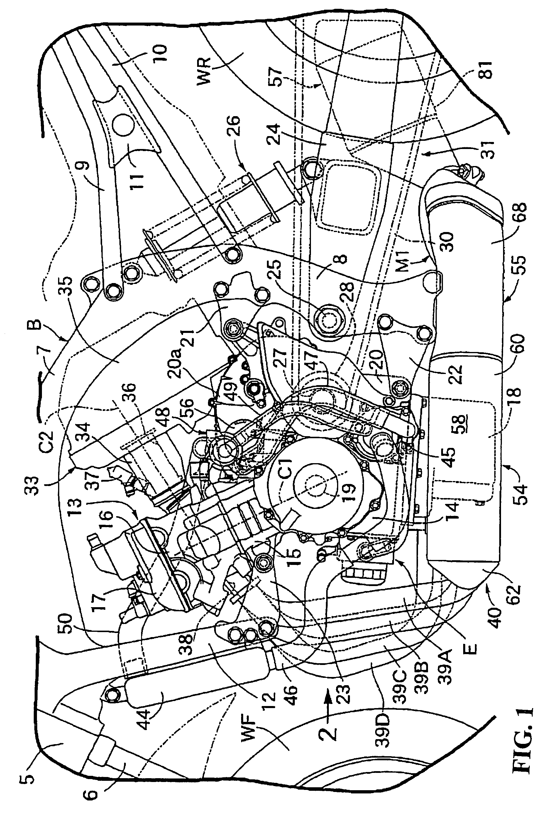
[0025]A first embodiment of the present invention will be described with reference to FIGS. 1 to 8. First, referring to FIG. 1, the vehicle body B of the motorcycle has a head pipe 5 at a front end thereof with a front fork 6 that pivotally supports a front wheel WF being supported by the head pipe 5 in a steering controllable fashion. Pivot frames 8 extend downwardly and are integrated with the rear portion of a pair of right and left main frames 7 that extend from the head pipe 5 toward the rear side. The front ends of the seat rails 9 extend rearwardly and upwardly and are coupled with the rear portions of both the main frames 7. The intermediate portions of the pivot frames 8 in the vertical direction are coupled with the front ends of the rear frames 10 that extend rearwardly and upwardly toward the lower side of the seat rails 9 with connecting members 11 being mutually connected between the seat rails 9 and the rear frames 10. In addition, the upper portions of engine hangers...


PUM


Abstract

In an exhaust system for a motorcycle in which an engine main body of a multi-cylinder engine has an oil pan on a lower portion thereof, and is mounted on a vehicle body with a plurality of expansion chambers being connected to a downstream side of an assembled portion of a plurality of exhaust pipes that extend out of the respective cylinders of the engine main body, respectively. The muffler includes a first expansion chamber that is connected to the assembled portion and the other expansion chambers that are the assembled portion are disposed on one side of the oil pan. The first continuous to the first expansion chamber. The respective exhaust pipes and expansion chamber is disposed on the other side of the oil pan with the other expansion chambers being disposed to the rear of the engine main body.

Description

CROSS-REFERENCE TO RELATED APPLICATIONS[0001]The present application claims priority under 35 USC 119 to Japanese Patent Application Nos. 2005-285937 filed on Sep. 30, 2005 and 2005-287128 filed on Sep. 30, 2005 the entire contents of which are hereby incorporated by reference.BACKGROUND OF THE INVENTION[0002]1. Field of the Invention[0003]The present invention relates to an exhaust system for a motorcycle in which an engine main body of a multi-cylinder engine has an oil pan on a lower portion thereof, and is mounted on a vehicle body, and a muffler having a plurality of expansion chambers connected to a downstream side of an assembled portion of the plurality of exhaust pipes that extend out of the respective cylinders of the engine main body, respectively.[0004]2. Description of Background Art[0005]An exhaust system for a motorcycle is known wherein a muffler is connected to the exhaust pipes extending from the respective cylinders of the multi-cylinder engine. The muffler is dis...

Claims


Application Information

Patent Timeline
Patent Type & Authority Patents(United States)
IPC IPC(8): B62D61/02F01N13/02
CPCF01N1/084F01N1/089F01N1/10F01N3/2885F01N13/02F01N2590/04Y02A50/20B62M7/02F01N1/00F01N13/00F01N13/08
Inventor TANIGUCHI, MASAYUKITSUTSUI, NORIYOSHIWAKITA, NOBUTAKATAKAMATSU, HIDETOSHIKASHIWABARA, YUJINAKAJIMA, SHUNICHIARIMA, TSUYOSHIHAZE, HIROTAKA
Owner HONDA MOTOR CO LTD
Why Eureka
Try Eureka