

Image forming device
a technology of forming device and forming plate, which is applied in the direction of thin material processing, article separation, transportation and packaging, etc., can solve the problems of large impulse and large impulsive sound generation, peripheral mechanism damage, and printing paper displacement, and achieve the effect of simple structur
- Summary
- Abstract
- Description
- Claims
- Application Information
AI Technical Summary
Benefits of technology
Problems solved by technology
Method used
Image

Examples
Embodiment Construction
[0017]With reference to the drawings, preferred embodiments of the present invention will be described.
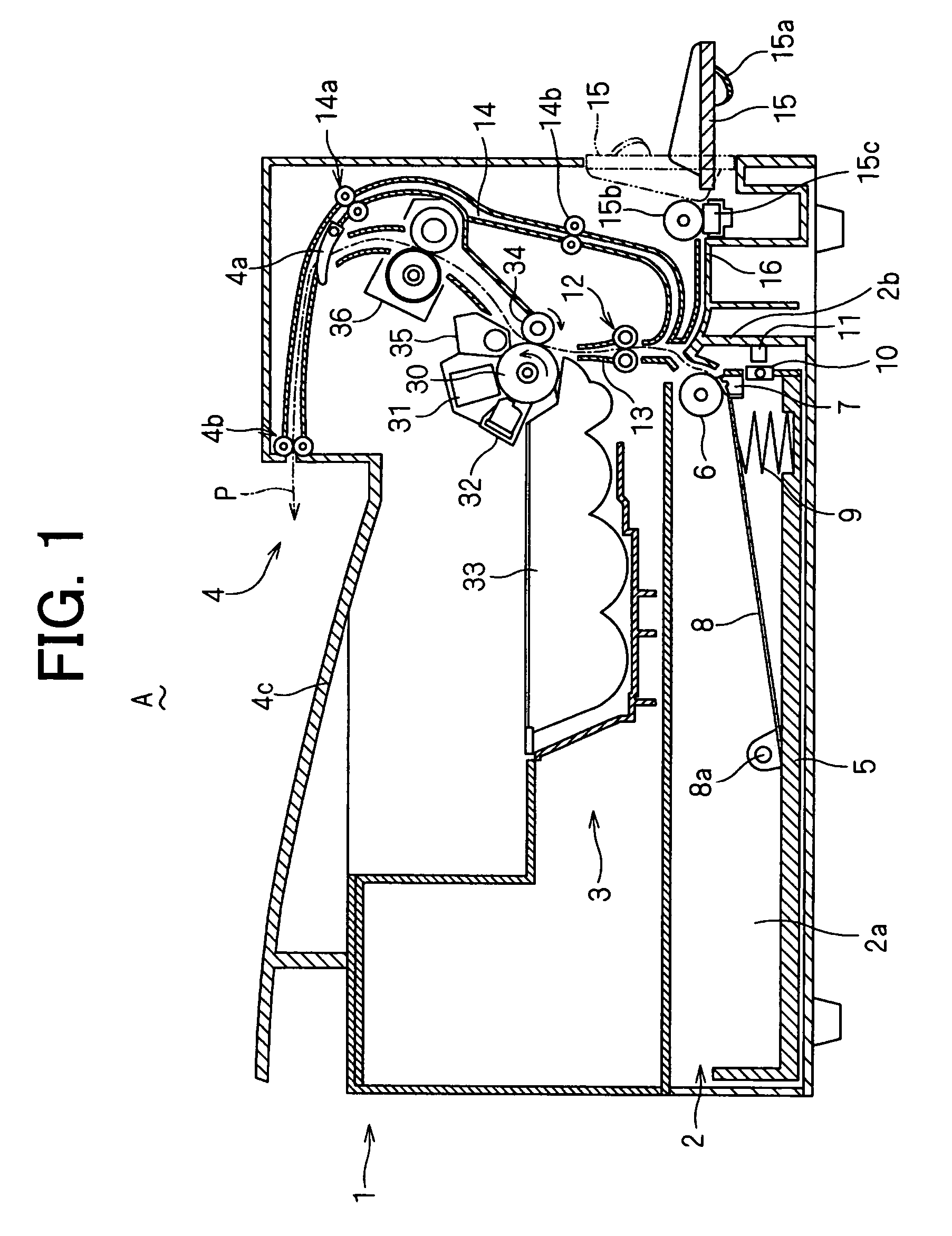
[0018]An image forming device (A) illustrated in FIG. 1 is a printer including an electrophotographic printing unit. The image forming device (A) is not limited to such an example. For example, the image forming device (A) may be a copier including an image scanner unit, a facsimile machine, or an MFP including a copy function and a facsimile function. In FIG. 1, a device main body 1 of the image forming device (A) includes a paper feed unit 2 accommodating printing papers, an electrophotographic printing unit 3, and an output unit 4 where printed papers are output. The paper feed unit 2, the printing unit 3 and the output unit 4 are vertically stacked in this order.
[0019]The paper feed unit 2 includes a cassette accommodating portion 2a. A paper feed cassette 5 is removably inserted in the cassette accommodating portion 2a in a direction perpendicular to the vertical direction of ...
PUM
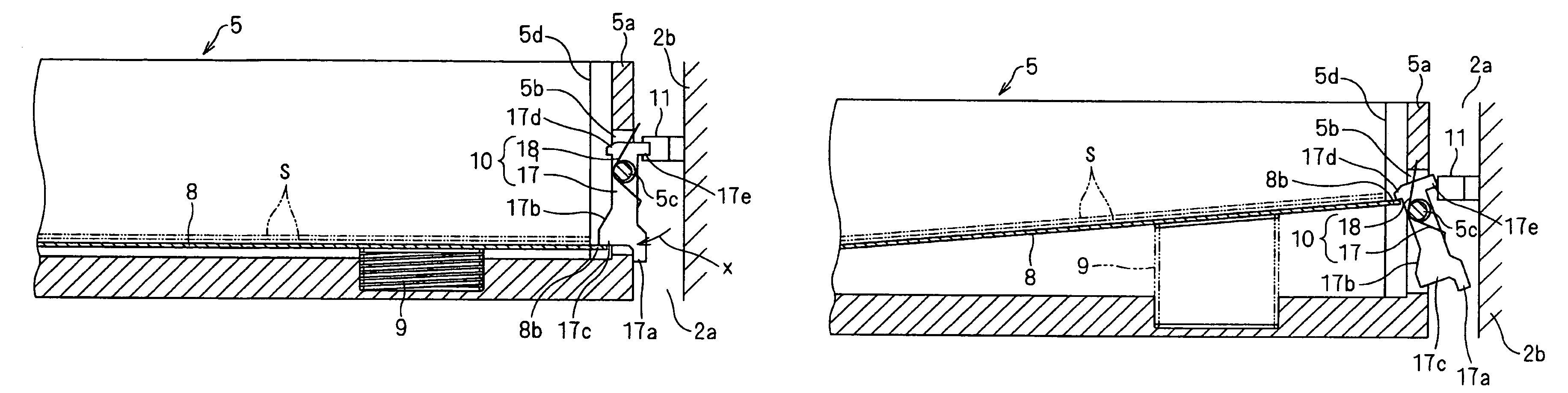
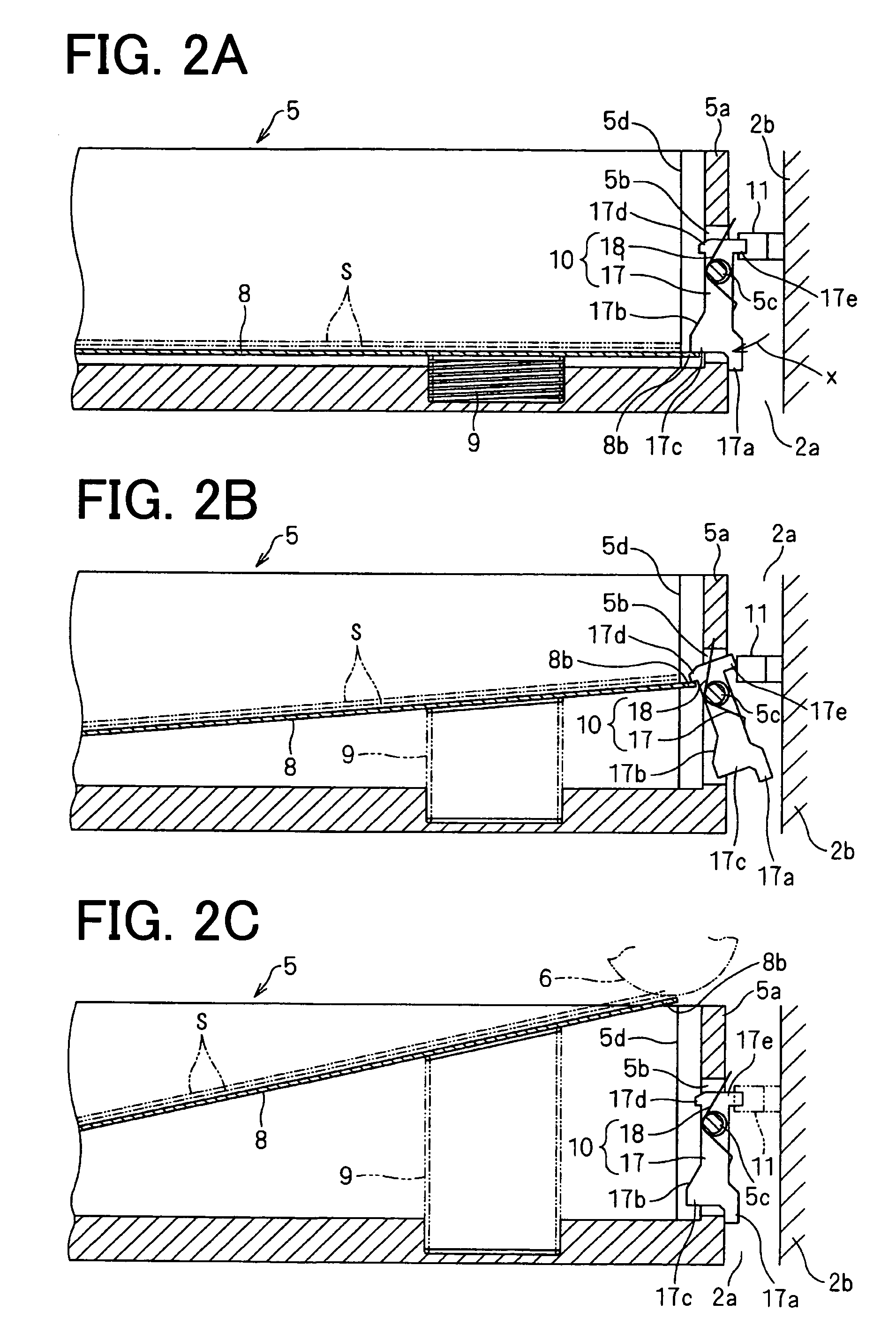
 Abstract
Description
Claims
Application Information