Safety door device of injection molding machine

a safe and injection molding machine technology, applied in the direction of latching locks, wing accessories, manufacturing tools, etc., can solve the problems of increasing costs, undue imposing a so as to achieve no great burden on the operator, the effect of ensuring safety and ensuring safety

Active Publication Date: 2009-06-02
FANUC LTD
View PDF8 Cites 3 Cited by
  • Summary
  • Abstract
  • Description
  • Claims
  • Application Information

AI Technical Summary

Benefits of technology

[0015]The present invention provides a safer safety door device of an injection molding machine without increasing costs, and further, without increasing the burden on the operator.
[0020]When the secondary safety door is closed shut, the primary safety door can be freely opened and closed independently of the secondary safety door so that there is no great burden on the operator. When the secondary safety door is open, the primary safety door is always open to provide safety. Further, both the primary safety door and the secondary safety door can be opened and closed separately; alternatively, the primary safety door and the secondary safety door can be moved together as a single body. In addition, if the primary safety door is closed shut then the secondary safety door is also always closed shut, and if the secondary safety door is opened in a state in which both the primary safety door and the secondary safety door are closed shut, the primary safety door opens, and further, in this case, the primary safety door and the secondary safety door are coupled together and move as a single body. Therefore, the primary safety door, which is not being operated, does not continue to move by itself under inertia, and the operation of the primary safety door can also be controlled by operation of the secondary safety door so that safety can be achieved.
[0021]When either the primary safety door or the secondary safety door is operated alone and both safety doors are moved, both safety doors are always coupled together and move as a single body, so that the safety door that is not being operated never becomes uncontrollable. In addition, when only one of the safety doors is moved, the moving safety door is of course one that is being operated by the operator, and therefore safety is achieved, and thus safety is attained in any case.

Problems solved by technology

However, since the clamping unit is designed to open and close the molds, there is a risk of an operator getting a hand caught in the molds.
However, such a single body structure increases the mass of the safety door, which is undesirable in that the safety door is opened and closed repeatedly when removing molded articles from the mold manually and thus imposes an undue burden on the operator.
However, there are drawbacks to the above-described approaches.
However, the coupling mechanism must be operated manually, and further, since the structure is such that both safety doors can open and close separately, it is necessary to provide detection switches to detect opening and closing of both safety doors in order to provide safety, which increases costs.

Method used


Image

  • Safety door device of injection molding machine
  • Safety door device of injection molding machine
  • Safety door device of injection molding machine

Examples


Embodiment Construction

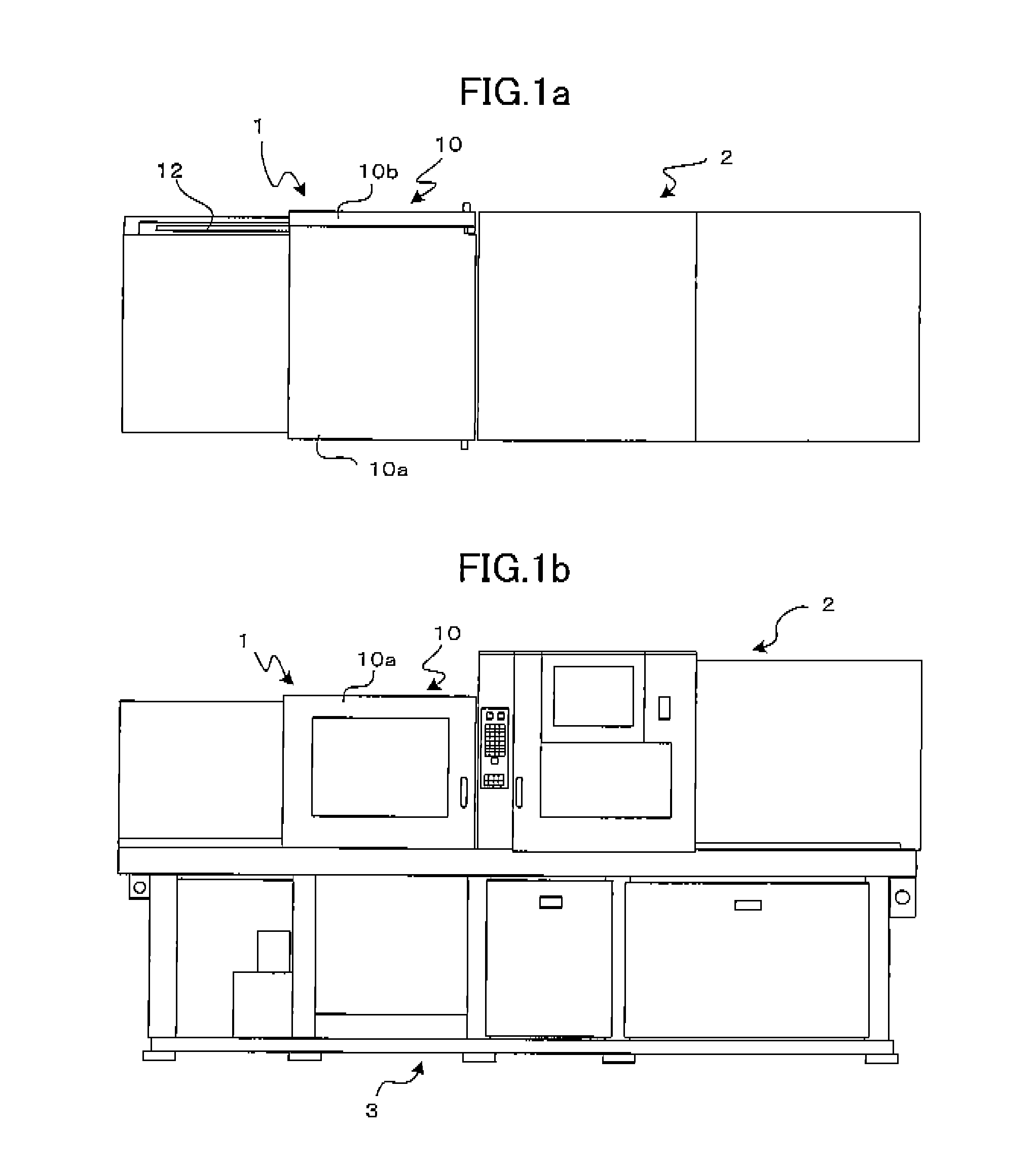
[0027]FIGS. 1a and 1b are schematic overall views showing plan and front views, respectively, of an injection molding machine provided with a safety door according to one embodiment of the present invention.

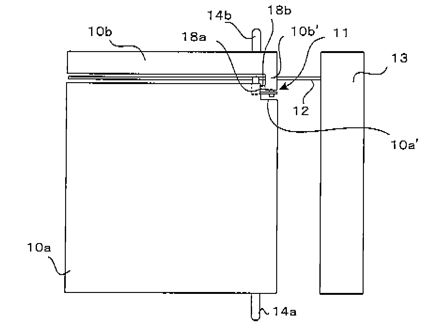
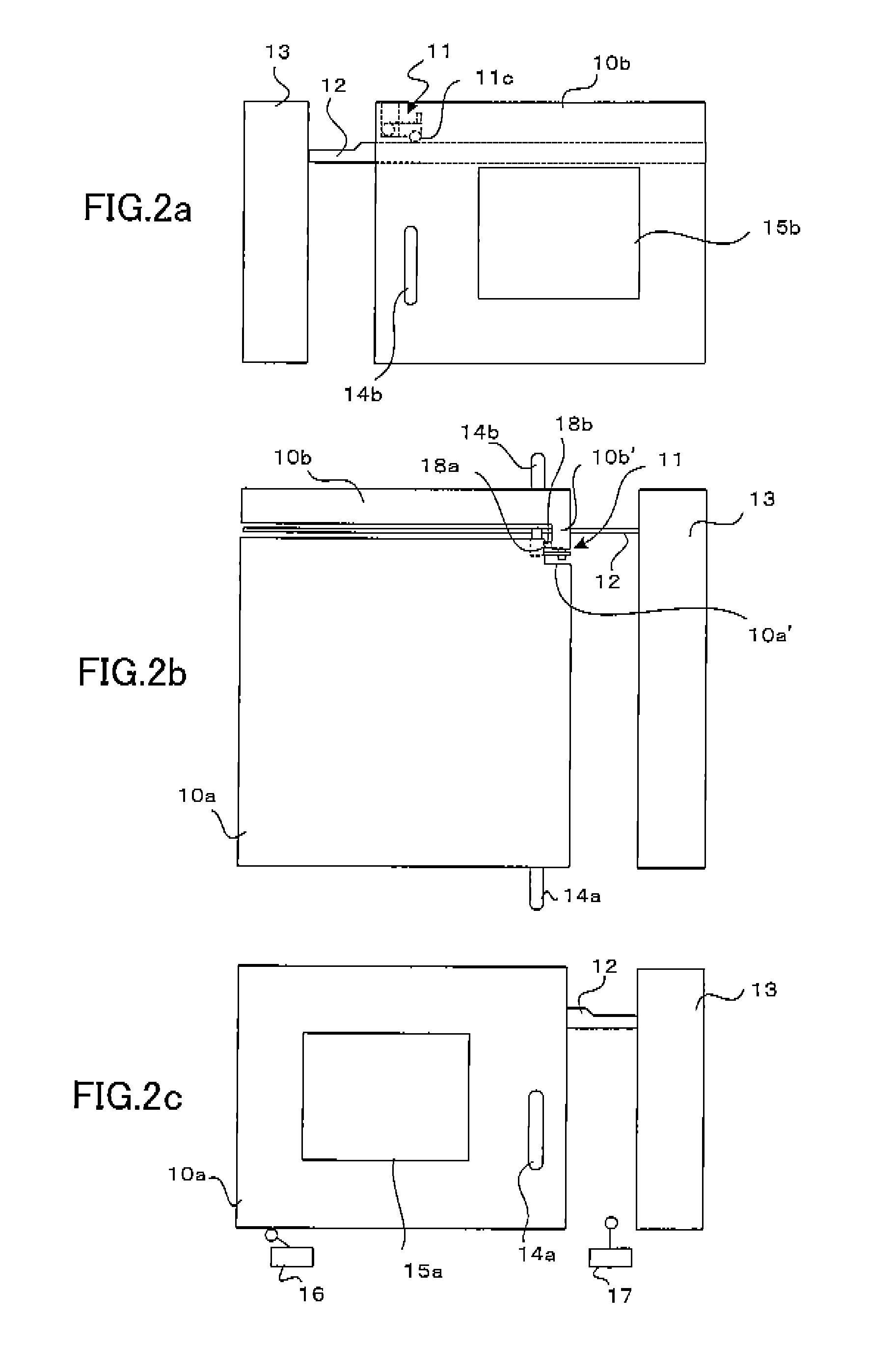
[0028]As shown in FIGS. 1a and 1b, a clamping unit 1 and an injection unit 2 are placed on a base 3 of the injection molding machine. A safety door device 10 is provided on the clamping unit 1. The safety door device 10 is configured so that a primary safety door 10a is provided on an operation side (front side) and a secondary safety door 10b is provided on a side opposite the operation side (rear side), in such a way that the primary safety door 10a and the secondary safety door 10b slide laterally in the drawing atop the base 3 so that the safety doors 10a, 10b can open and close. The primary safety door 10a is a safety door bent so as to open and close the front side and a top side.

[0029]FIGS. 1a and 1b show the clamping unit 1 closed. By moving the primary safety door 10a to...


PUM

PropertyMeasurementUnit
distanceaaaaaaaaaa
massaaaaaaaaaa
angleaaaaaaaaaa

Abstract

A safer safety door, provided at low cost and imposing little burden on an operator. A primary safety door with a top and a secondary safety door are provided on a clamping unit. The primary safety door and the secondary safety door abut each other at abutting portions provided on each safety door. The secondary safety door has an engaging member that swings along a guide member. The engaging member has a hinge bent in one direction. When both safety doors are closed, the primary safety door can be freely opened and closed independently. When the secondary safety door is opened, both safety doors are linked together and move as a single body. In the state where the primary and secondary safety doors are opened separately, when the primary safety door is moved to be closed, the hinge member bends and both safety doors are linked together as a unit.

Description

[0001]The present application is based on, and claims priority from, Japanese Application Number 2007-026021, filed Feb 5, 2007, the disclosure of which is hereby incorporated by reference herein in its entirety.BACKGROUND OF THE INVENTION[0002]1. Field of the Invention[0003]The present invention relates to a safety door device provided on a mold clamping unit of an injection molding machine.[0004]2. Description of the Related Art[0005]In an injection molding machine, a clamping unit moves a movable mold mounted on a movable platen against a stationary mold mounted on a stationary platen, closes the molds, and injects resin into the molds, after which the clamping unit is moved, the molds opened, and the molded article removed. When mounting the molds on the clamping unit, when performing maintenance on the clamping unit, and further, when removing the molded article manually, it is necessary to be able to access the clamping unit from the outside. However, since the clamping unit i...

Claims


Application Information

Patent Timeline
Patent Type & Authority Patents(United States)
IPC IPC(8): B29C45/84
CPCB22D17/20B29C45/84Y10T70/5173
Inventor NISHIMURA, KOICHISHIMA, KOJI
Owner FANUC LTD
Why Eureka
Try Eureka