Capacitive sensor

Inactive Publication Date: 2009-06-02
GENERALPLUS TECH INC
View PDF13 Cites 28 Cited by
  • Summary
  • Abstract
  • Description
  • Claims
  • Application Information

AI Technical Summary

Benefits of technology

[0012]In view of this, it is therefore an object of the invention to pr

Problems solved by technology

However, the conventional capacitive sensors tend to be influenced by the external electric field and the interference of the alternating current power.
Because the conventional capacitive sensor measures the equivalent capacitance of the sensing electrod

Method used


Image

  • Capacitive sensor
  • Capacitive sensor
  • Capacitive sensor

Examples


Embodiment Construction

[0038]The present invention will be apparent from the following detailed description, which proceeds with reference to the accompanying drawings, wherein the same references relate to the same elements.

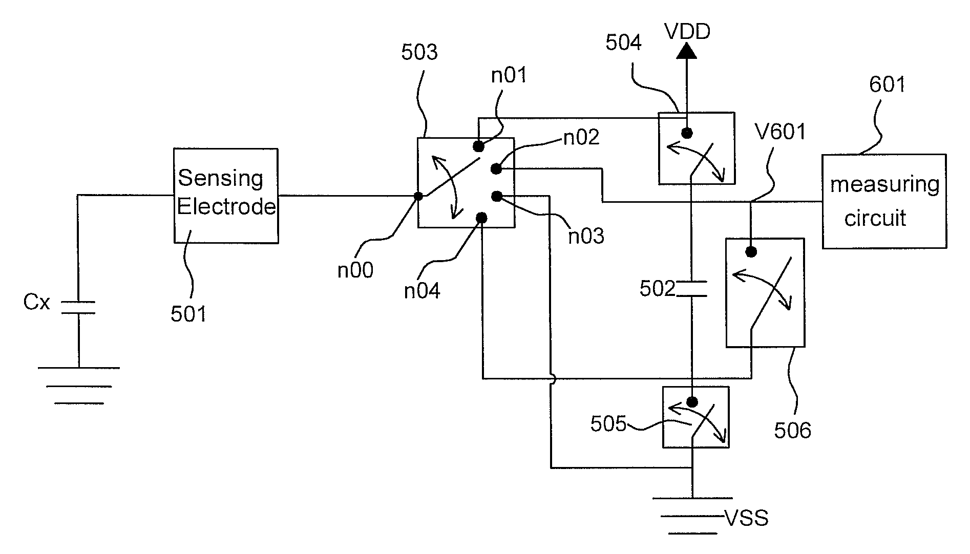
[0039]FIG. 5 is a circuit diagram showing a capacitive sensor according to an embodiment of the invention. Referring to FIG. 5, the capacitive sensor includes a sensing electrode 501, a sensing capacitor 502, a first switch element 503, a second switch element 504, a third switch element 505 and a fourth switch element 506. In order to describe the operation of this embodiment, nodes n00, n01, n02, n03 and n04, and common voltages VDD and VSS are labeled in FIG. 5. In order to make one of ordinary skill in the art understand the spirit of this invention, it is assumed that the common voltage VDD is a power voltage, and the common voltage VSS is a ground voltage in this embodiment. The circuit connection relationship of this capacitive sensor is illustrated in the drawing.

[0040]Regardi...


PUM


Abstract

In a capacitive sensor, a sensing electrode is positively charged, the sensing electrode and a sensing capacitor are charge-balanced, the sensing electrode is negatively charged, and then the sensing electrode and the sensing capacitor are again charge-balanced. The sensing electrode is positively and negatively charged in the same period when the capacitive sensor is sensed. So, the invention can not only effectively improve the high-frequency external interference but also effectively resist the interference when an external direct current electrical field approaches.

Description

[0001]This application claims priority of No. 097116418 filed in Taiwan R.O.C. on May 5, 2008 under 35 USC 119, the entire content of which is hereby incorporated by reference.BACKGROUND OF THE INVENTION[0002]1. Field of Invention[0003]The invention relates in general to a touch sensor, and more particularly to a capacitive sensor with the immunity from the alternating Current power.[0004]2. Related Art[0005]Recently, many control buttons, such as buttons of an elevator or buttons of an electronic game console, have been changed from the conventional mechanical spring buttons into touch sensors due to the progress of the technology. FIG. 1 is a circuit diagram showing a conventional capacitive sensor. Referring to FIG. 1, the circuit includes a sensing electrode 101, a resistor 102 and a sense-control end 103. In this circuit, the sensing electrode 101 corresponds to a grounded capacitor.[0006]FIG. 2 shows operation waveforms at the node A between the sensing electrode 101 and the r...

Claims


Application Information

Patent Timeline
IPC IPC(8): G01R27/26
CPCG06F3/044H03K17/962H03K2217/960705H03K2217/960725G06F3/04166
Inventor LIAO, TUNG-TSAILO, LI SHENG
Owner GENERALPLUS TECH INC
Why Eureka
Try Eureka