Polarization switching/variable directivity antenna

a variable directivity, polarization switching technology, applied in the field of antennas, can solve the problems of generating a completely circularly polarized, elliptically polarized wave, deteriorating communication quality, etc., and achieve good axial ratio characteristics

Inactive Publication Date: 2009-06-02
PANASONIC CORP
View PDF24 Cites 5 Cited by
  • Summary
  • Abstract
  • Description
  • Claims
  • Application Information

AI Technical Summary

Benefits of technology

[0020]The present invention solves the aforementioned conventional problems, and an objective thereof is to provide an antenna having a construction in which no phase shifter is used and there is only a single feed line so that there is no need for switching, thus simultaneously realizing switching of a maximum gain direction of radiation directivity of the antenna and switching of the rotation direction of a circularly polarized wave, with good axial ratio characteristics in the maximum gain direction.
[0044]the second slot is continuous with the first slot via a third slot.Based on the above construction, it is possible to simultaneously achieve switching of the maximum gain direction and switching of the rotation direction of a circularly polarized wave in the maximum gain direction.
[0045]Further preferably, the circular polarization index Q0 is no less than 2.7 and no more than 3.2. Under this condition, further better circularly polarized wave characteristics can be obtained.
[0047]A polarization switching / variable directivity antenna of the present invention realizes, in a simple construction which uses no phase shifters, switching of a maximum gain direction of radiation directivity and switching of the rotation direction of a circularly polarized wave which has good axial ratio characteristics along the maximum gain direction.

Problems solved by technology

This multipath propagation is a cause for deterioration of the communication quality.
Usually, it is difficult to generate a completely circularly polarized wave, because it will merge with a polarization component of the opposite rotation, thus resulting in an elliptically polarized wave.
However, as an antenna to be internalized in a laptop computer or an antenna for a mobile device, circular polarization antennas such as those shown in FIGS. 15B and 15C are unsuitable.
The position and orientation of such a mobile terminal may greatly change, so that a circular polarization antenna having a fixed rotation direction may not be able to perform transmission / reception when it is reversed in orientation, for example.
However, an antenna having the above-described conventional construction is unsuitable as an antenna for a small-sized device or terminal because of problems such as: a plurality of phase shifters being required, thus resulting in complicated construction and control, and switching of a plurality of feed lines being required, thus resulting in a large insertion loss associated with switching elements.

Method used


Image

  • Polarization switching/variable directivity antenna
  • Polarization switching/variable directivity antenna
  • Polarization switching/variable directivity antenna

Examples


embodiment 1

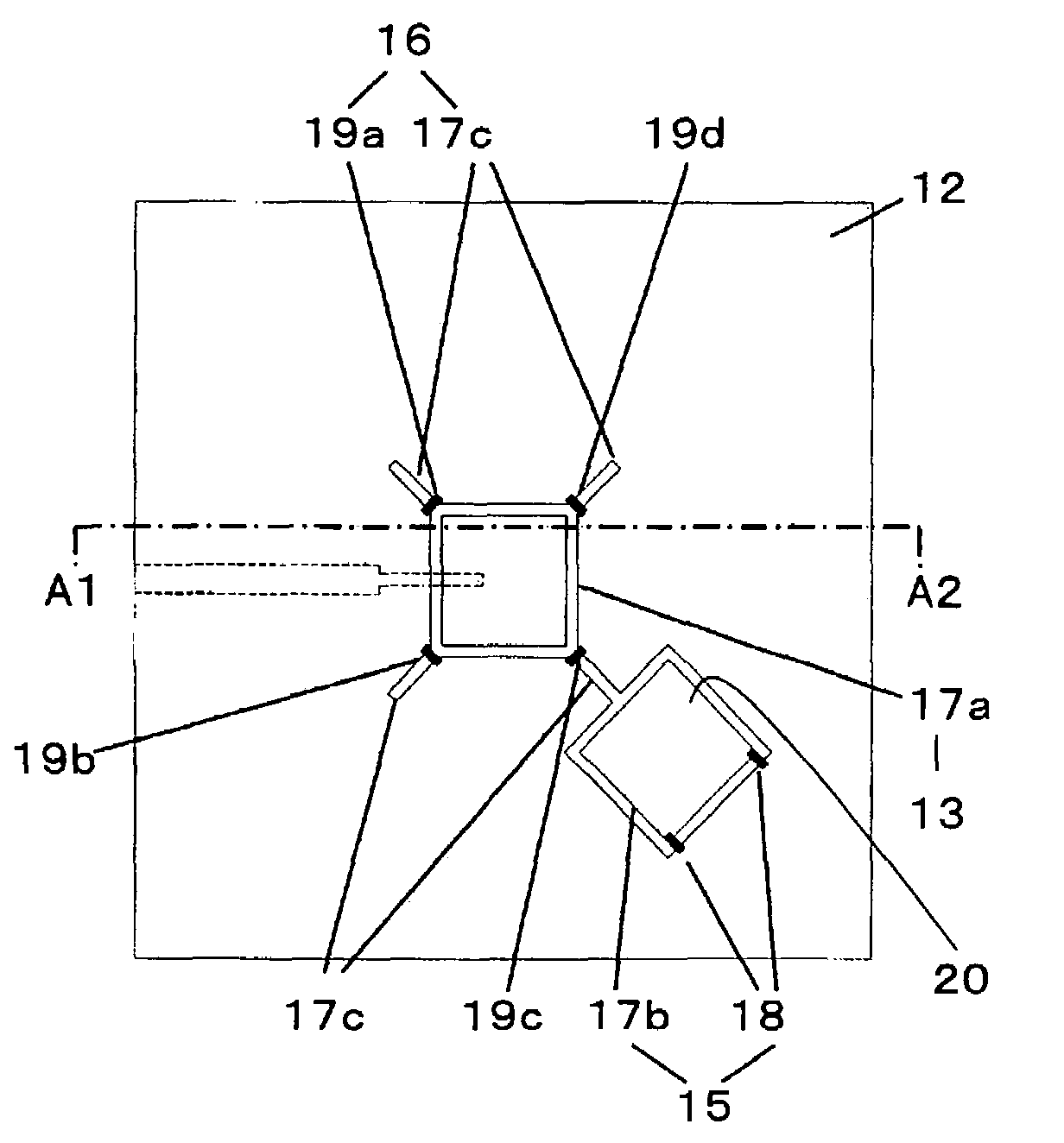
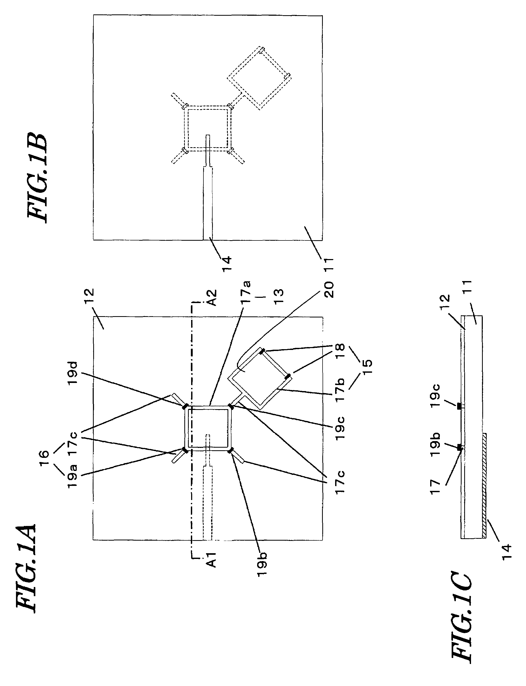
[0066]First, FIGS. 1A to 1C, which illustrate Embodiment 1 of the present invention, will be referred to FIG. 1A is a see-through view of a first surface (hereinafter, “front face”) of a dielectric substrate 11. FIG. 1B is a see-through view of a second surface (hereinafter, “rear face”) of the dielectric substrate 11 which opposes the first surface. FIG. 1C is a cross-sectional view taken along line A1-A2 in FIG. 1A.

[0067]As shown in FIG. 1, the antenna of the present embodiment includes a ground conductor plate 12 on the front face of the dielectric substrate 11. A loop-shaped first slot 17a, a loop-shaped second slot 17b, and linear-shaped third slots 17c are provided in the ground conductor plate 12. The slot 17b has at least two directivity switching switches 18 provided thereon, and each slot 17c has at least one polarization switching switch (19a to 19d) provided thereon. A feed member 14 is provided on the rear face of the dielectric substrate 11. Switching of the maximum ga...

example 1

[0103]Hereinafter, Example 1 of the present invention will be described. The antenna of Example 1 has the construction shown in FIGS. 1A to 1C, and an enlarged view of the neighborhood of the first slot 17a is as shown in FIG. 3. The constituent elements of Example 1 are as shown in Table 3.

[0104]

TABLE 3dielectricdielectric constant: 2.08substrate 11size: 130.0 × 130.0 × 3.2 mmfirst slot 17asquarelength L1 of one side: 25.0 mmslot width w1: 2.0 mmsecond slot 17bsquarelength L2 of one side: 22.0 mmslot width w2: 3.0 mmthird slot 17clength L3 of one side: 10.0 mmslot width w3: 4.0 mm

[0105]In this case, the Q0 of the radiation element 13 is calculated to be 5.55, with the circular polarization index being about 3.1. In Example 1, the directivity switching element is allowed to function as a director.

[0106]FIGS. 7A, 7B, and 7C are diagrams showing examples of how the directivity switching switches 18 and the polarization switching switches 19a to 19d may be controlled in order to change...

embodiment 2

[0116]Hereinafter, with reference to the drawings, a polarization switching / variable directivity antenna according to Embodiment 2 of the present invention will be described.

[0117]FIG. 10 is a see-through view of a first substrate surface (front face) according to Embodiment 2 of the present invention. Portions which are drawn by broken lines are meant to be formed on a second substrate surface (rear face). The detailed description of any portion that has an identical counterpart in Embodiment 1 will be omitted.

[0118]In the polarization switching / variable directivity antenna of Embodiment 2, every third slot 17c defining a polarization switching element 16 has a second slot (24a to 24d) of a directivity switching element 15 connected thereto, at an end that is not continuous with a first slot 17a. Moreover, a second polarization switching switch (26a to 26d) is connected at each position adjoining a second slot (24a to 24d), so as to bridge across the third slot 17c.

[0119]In Embodi...


PUM


Abstract

A polarization switching / variable directivity antenna according to the present invention includes a ground conductor plate 12 on a surface of a dielectric substrate 11, and has a radiation element 13, a directivity switching element 15, and polarization switching elements 16 provided on the ground conductor plate 12 side of the dielectric substrate 11. The radiation element 13 includes a first slot 17a formed by removing a loop-like portion from the ground conductor plate 12. The directivity switching element 15 includes a second slot 17b formed by removing a loop-like portion from the ground conductor plate 12 and directivity switching switches 18. The polarization switching elements 16 includes a third slot 17c formed by removing a linear-shaped portion from the ground conductor plate 12 and polarization switching switches 19a to 19d. Through control of the directivity switching switches 18, switching of a maximum gain direction of radiation directivity of the antenna is realized. Through control of the polarization switching switches 19a to 19d, switching of a rotation direction of a circularly polarized wave which is emitted from the antenna can be realized.

Description

[0001]This is a continuation of International Application No. PCT / JP2007 / 069756, with an international filing date of Oct. 10, 2007, which claims priority of Japanese Patent Application No. 2006-304733, filed on Nov. 10, 2006, the contents of which are hereby incorporated by reference.BACKGROUND OF THE INVENTION[0002]1. Field of the Invention[0003]The present invention relates to an antenna which is suitable for high-quality wireless communications in the microwave and extremely high frequency ranges, where communications are performed while switching the rotation direction of a circularly polarized wave and a maximum gain direction of radiation directivity.[0004]2. Description of the Related Art[0005]In recent years, there are increasing needs for rapid large-capacity communications in a closed space, e.g., an indoor space, as exemplified by indoor wireless LAN, for example. In a closed space such as an indoor space, there are not only direct waves along a line-of-sight between ant...

Claims


Application Information

Patent Timeline
Patent Type & Authority Patents(United States)
IPC IPC(8): H01Q13/00
CPCH01P1/161H01P1/165H01Q3/24H01Q13/10H01Q21/245
Inventor MATSUSHITA, AKIOFUJISHIMA, TOMOYASU
Owner PANASONIC CORP
Why Eureka
Try Eureka