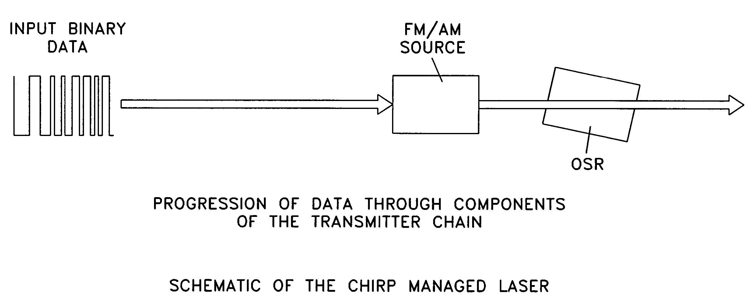
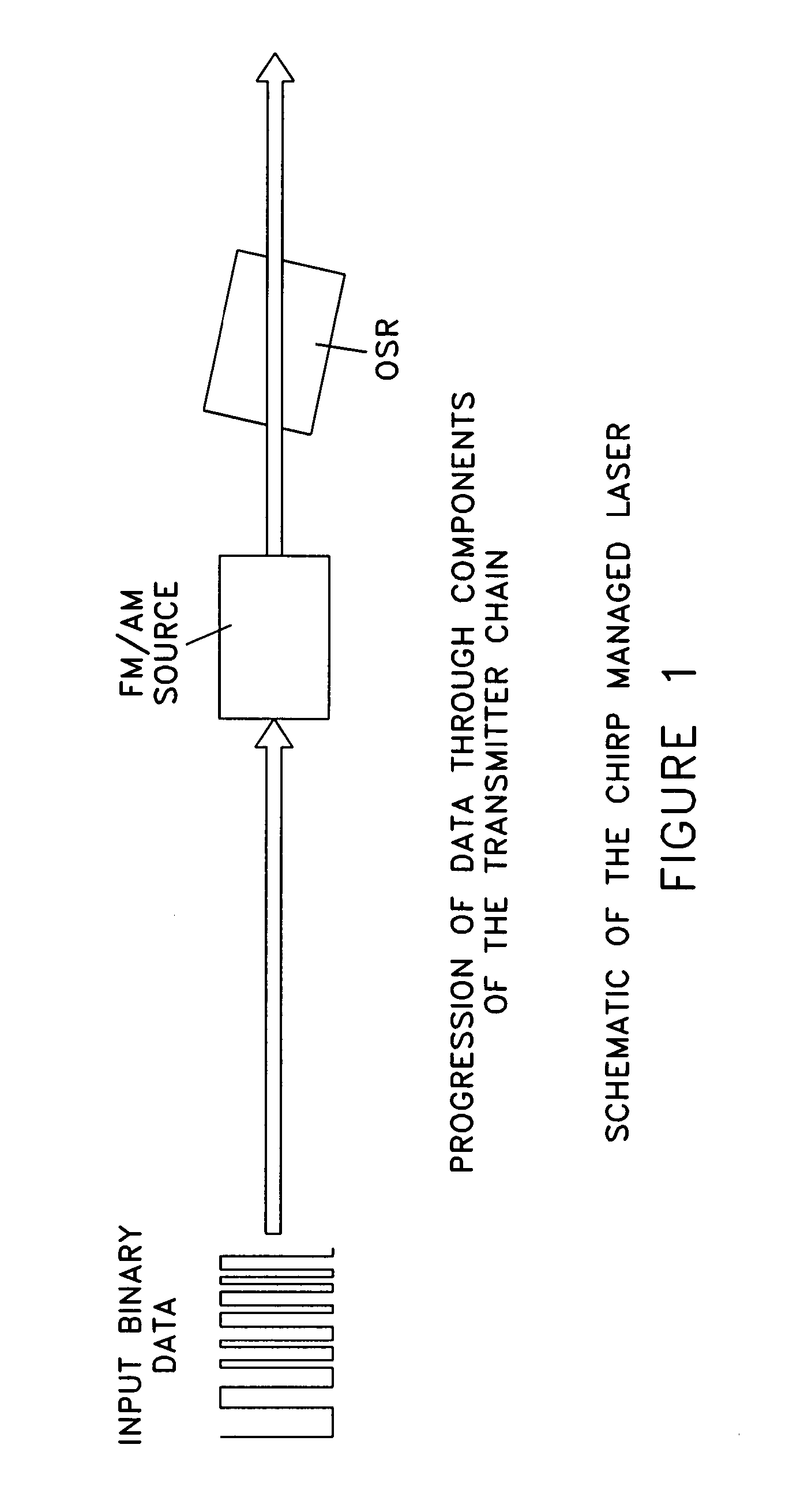
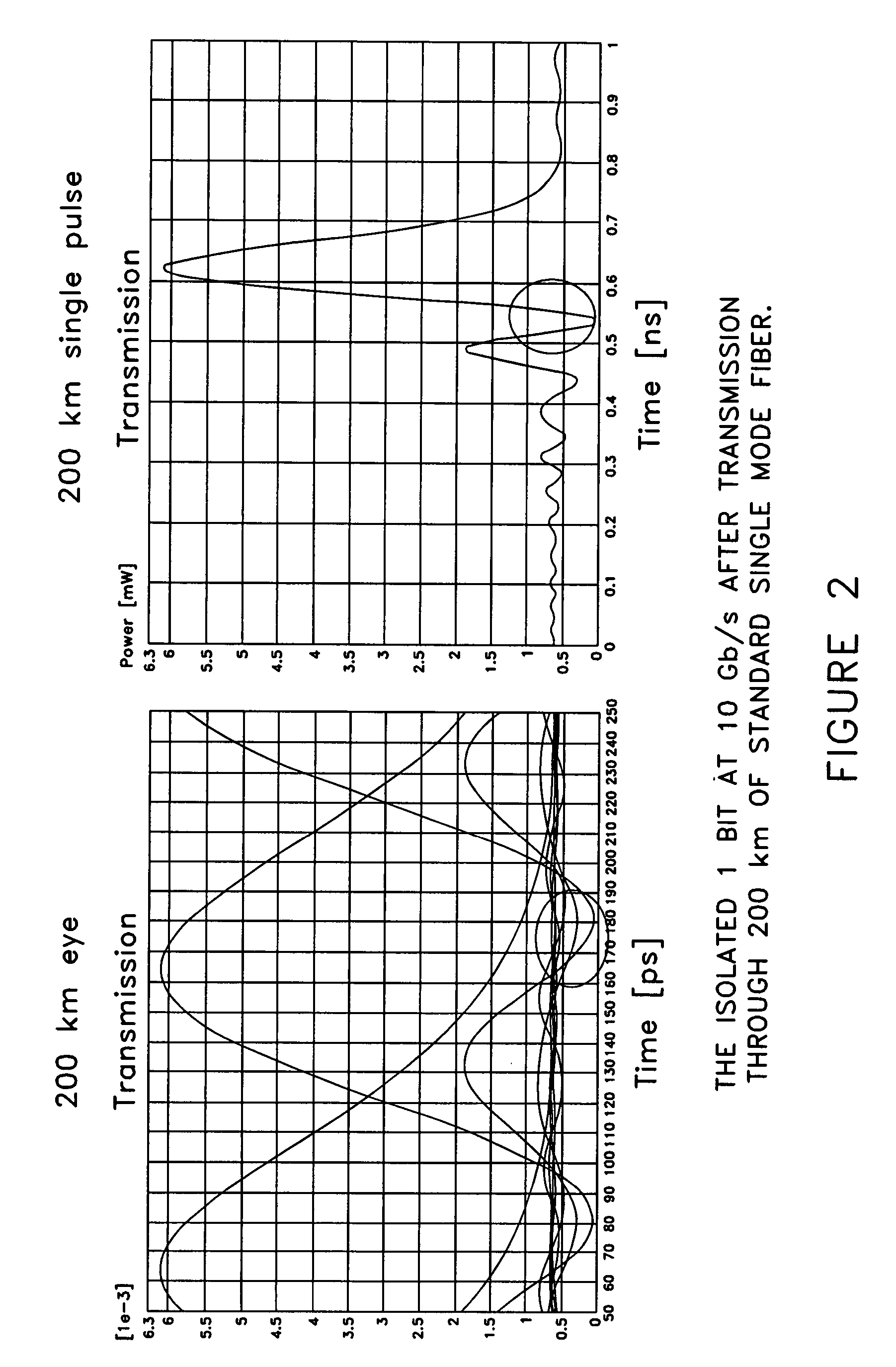
Chirp Managed Laser (CML) transmitter

a laser transmitter and laser management technology, applied in electromagnetic transmission, electrical equipment, transmission, etc., can solve the problems of reducing the overall bit error rate of the transmitted signal, and increasing the transmission length through dispersive fibers, etc.

Inactive Publication Date: 2009-06-02
II VI DELAWARE INC
View PDF80 Cites 22 Cited by
  • Summary
  • Abstract
  • Description
  • Claims
  • Application Information

AI Technical Summary

Benefits of technology

[0017]We have recently discovered that the overall bit error rate of the transmitted signal can be further reduced, and the transmission length through dispersive fiber can be further increased, if the frequency excursion of the modulated signal is adjusted to have the following relation to the fiber length, bit rate and dispersion:D×L×ΔνAD˜T.  (1)Here D is the dispersion of the fiber in ps / GHz / km, L is fiber length in km, ΔνAD is the frequency excursion of the transmitted signal at the output of the chirp managed laser in GHz, and T is the bit period in picoseconds.
[0027]the frequency excursion of the first signal, ΔνAD, in GHz is adjusted such that it is substantially equal to the ratio of the bit period of the digital base signal, T, in picoseconds, to the product of the transmission fiber length, L, in km, and the dispersion of the transmission fibers, D, in ps2 / km, whereby to reduce the bit error rate at transmission distance L.
[0038]the frequency excursion of the first signal, ΔνAD, in GHz is adjusted such that it is substantially equal to the ratio of the bit period of the digital base signal, T, in picoseconds, to the product of the transmission fiber length, L, in km, and the dispersion of the transmission fibers, D, in ps2 / km, whereby to reduce the bit error rate at transmission distance L.

Problems solved by technology

On the other hand, directly modulated lasers (DML) reach <5 km because their inherent time dependent chirp causes severe distortion of the signal after this distance.

Method used


Image

  • Chirp Managed Laser (CML) transmitter
  • Chirp Managed Laser (CML) transmitter
  • Chirp Managed Laser (CML) transmitter

Examples


Embodiment Construction

[0045]In accordance with the present invention, it has now been discovered that the overall bit error rate of the transmitted signal can be further reduced, and the transmission length through dispersive fiber can be further increased, if the frequency excursion of the modulated signal is adjusted to have the following relation to the fiber length, bit rate and dispersion:

D×L×ΔνAD˜T.  (1)

Here D is the dispersion of the fiber in ps2 / km, L is fiber length in km, ΔνAD is the frequency excursion of the transmitted signal at the output of the chirp managed laser in GHz, and T is the bit period in picoseconds.

[0046]The increased distance may come at the cost of reducing the bit error rate at the transmitter output. More particularly, Equation (1) states that the optimum frequency excursion for the transmitted signal is to be chosen for a particular dispersion such that the blue shifted frequency of the chirp is translated by one bit. Note that our simulations and experiments show that the...


PUM


Abstract

A fiber optic communication system comprising:an optical signal source adapted to receive a binary base signal having a bit period T, and generate a first signal, wherein the first signal is frequency modulated; andan optical spectrum reshaper (OSR) adapted to reshape the first signal into a second signal, wherein the second signal is amplitude modulated and frequency modulated;characterized in that:the frequency excursion of the first signal is adjusted such that the frequency excursion is substantially equal to the ratio of the bit period of the digital base signal to total dispersion of the transmission fiber, whereby to increase the tolerance of the second signal to dispersion in a transmission fiber.

Description

REFERENCE TO PENDING PRIOR PATENT APPLICATIONS[0001]This patent application:[0002](i) is a continuation-in-part of pending prior U.S. patent application Ser. No. 11 / 272,100, filed Nov. 8, 2005 by Daniel Mahgerefteh et al. for POWER SOURCE FOR A DISPERSION COMPENSATION FIBER OPTIC SYSTEM;[0003](ii) is a continuation-in-part of pending prior U.S. patent application Ser. No. 10 / 308,522, filed Dec. 3, 2002 by Daniel Mahgerefteh et al. for HIGH-SPEED TRANSMISSION SYSTEM COMPRISING A COUPLED MULTI-CAVITY OPTICAL DISCRIMINATOR;[0004](iii) is a continuation-in-part of pending prior U.S. patent application Ser. No. 11 / 441,944, filed May 26, 2006 by Daniel Mahgerefteh et al. for FLAT DISPERSION FREQUENCY DISCRIMINATOR (FDFD);[0005](iv) is a continuation-in-part of pending prior U.S. patent application Ser. No. 11 / 068,032, filed Feb. 28, 2005 by Daniel Mahgerefteh et al. for OPTICAL SYSTEM COMPRISING AN FM SOURCE AND A SPECTRAL RESHAPING ELEMENT;[0006](v) is a continuation-in-part of pending p...

Claims


Application Information

Patent Timeline
Patent Type & Authority Patents(United States)
IPC IPC(8): H04B10/04
CPCH04B10/504H04B10/516H04B10/5561H04B2210/517
Inventor MATSUI, YASUHIROMAHGEREFTEH, DANIEL
Owner II VI DELAWARE INC
Why Eureka
Try Eureka